
Books in 2015 - Part 1
Andrew Schmitt, founder and CEO at Cignal AI
I didn’t read that much this year but I did read The Wright Brothers by David McCullough. That was outstanding. McCullough is a great historical author and wrote a book that was both a biography of the Wrights as well as a narrative of their efforts to build the first powered airplane.
I didn't know of all of the other simultaneous, better-financed efforts that fell far short of the efforts of two brothers from Dayton, Ohio. I also was unaware of how the effort transfixed the world when they did complete it.
There is so much chattering today about Lean Development and Devops (how many people use that word and really know what it means?) as if these are new developments. But the Wrights are a case study in lean development and simultaneous development and deployment. Read this and see Devops in action over 100 years ago and I'm sure there are lots more examples.
Rupert Baines, CEO at UltraSoC
This year has been rather frantic: starting a new role and being very full on has meant I've read less than I usually do. Perhaps that's wrong: a friend and mentor advises this precisely is the time to read more, for sanity and perspective. But she is wiser than I, or perhaps more self-disciplined.
Inevitably, reading less does not mean buying less! The Japanese have a term which is not yet a loanword but ought to be: Tsundoku.
Many of the books I have read have been non-taxing but fun (Trigger Mortis: the new James Bond; The Martian; Robert Harris' Cicero trilogy etc.) but I have read a few brilliant books worth recommending.
The Narrow Road To The Deep North by Richard Flanagan deservedly won the Booker prize last year and is a lovely, haunting, tragic novel. It describes an Australian surgeon who is captured and becomes a war hero as commander of a Japanese PoW camp - and the consequences for him and others after the war. It is not an easy read, harrowing and sad. But brilliant scenes, astonishingly vivid characters and insights on what it means to be "a good man" and the effect of war make the hard work worthwhile. A brilliant book.
A Place of Greater Safety by Hilary Mantel. I loved Wolf Hall (if you haven't read it, then do so) so read her earlier historic novel. Thank God for e-books because this is huge - and if I had realised how hefty it was I might not have read it. Set in the French Revolution, this describes in feverish intensity and hyper-real vividness the run-up to revolution, the Bastille and then the Terror. Robespierre, St. Just, Danton, and many, many more feature in utterly fascinating, compelling detail. There is a lot of information, and a LOT of pages but fascinating and enjoyable.
I really enjoy David Mitchell's novels. A clever, complex, interwoven set of stories (within the books and between them). The Bone Clocks was a fun novel: flitting through characters and decades (1984-2043) in a gripping science fiction/ adventure romp. Slade House is a shorter Halloween horror-ride of a creepy page-turner.
In non-fiction, it is interesting I haven't read much this year.
I finally read Thinking, Fast and Slow by Daniel Kahneman. To be honest, it is a fascinating insight but suffers the fault of so many business books: it has one great idea, but that isn't enough to support a whole book. Reading it late and being aware of that idea I found myself turning pages rather fast as a familiar concept was explained and repeated. That is perhaps ironic in a book about modes of thinking and contrasting quick impressions with deeper reflection.
A slight cheat as I haven't read them yet (remember what I said about book piles?), are SuperForecasting: The Art and Science of Forecasting by Philip Tetlock and Dan Gardner and Act Like a Leader, Think Like a Leader by Herminia Ibarra.
Both were highly recommended by several people independently. Both have travelled the world on my Kindle without being started yet. Maybe over the holidays.
For Part 2, click here
SDM and MIMO: An interview with Bell Labs
Part 2: The capacity crunch and the role of SDM
The argument for spatial-division multiplexing (SDM) - the sending of optical signals down parallel fibre paths, whether multiple modes, cores or fibres - is the coming ‘capacity crunch’. The information-carrying capacity limit of fibre, for so long described as limitless, is being approached due to the continual yearly high growth in IP traffic. But if there is a looming capacity crunch, why are we not hearing about it from the world’s leading telcos?
“It depends on who you talk to,” says Peter Winzer, head of the optical transmission systems and networks research department at Bell Labs. The incumbent telcos have relatively low traffic growth - 20 to 30 percent annually. “I believe fully that it is not a problem for them - they have plenty of fibre and very low growth rates,” he says.
Twenty to 30 percent growth rates can only be described as ‘very low’ when you consider that cable operators are experiencing 60 percent year-on-year traffic growth while it is 80 to 100 percent for the web-scale players. “The whole industry is going through a tremendous shift right now,” says Winzer.
In a recent paper, Winzer and colleague Roland Ryf extrapolate wavelength-division multiplexing (WDM) trends, starting with 100-gigabit interfaces that were adopted in 2010. Assuming an annual traffic growth rate of 40 to 60 percent, 400-gigabit interfaces become required in 2013 to 2014, and the authors point out that 400-gigabit transponder deployments started in 2013. Terabit transponders are forecast in 2016 to 2017 while 10 terabit commercial interfaces are expected from 2020 to 2024.
In turn, while WDM system capacities have scaled a hundredfold since the late 1990s, this will not continue. That is because systems are approaching the Non-linear Shannon Limit which estimates the upper limit capacity of fibre at 75 terabit-per-second.
Starting with 10-terabit-capacity systems in 2010 and a 30 to 40 percent core network traffic annual growth rate, the authors forecast that 40 terabit systems will be required shortly. By 2021, 200 terabit systems will be needed - already exceeding one fibre’s capacity - while petabit-capacity systems will be required by 2028.
Even if I’m off by an order or magnitude, and it is 1000, 100-gigabit lines leaving the data centre; there is no way you can do that with a single WDM system
Parallel spatial paths are the only physical multiplexing dimension remaining to expand capacity, argue the authors, explaining Bell Labs’ interest in spatial-division multiplexing for optical networks.
If the telcos do not require SDM-based systems anytime soon, that is not the case for the web-scale data centre operators. They could deploy SDM as soon as 2018 to 2020, says Winzer.
The web-scale players are talking about 400,000-server data centres in the coming three to five years. “Each server will have a 25-gigabit network interface card and if you assume 10 percent of the traffic leaves the data centre, that is 10,000, 100-gigabit lines,” says Winzer. “Even if I’m off by an order or magnitude, and it is 1000, 100-gigabit lines leaving the data centre; there is no way you can do that with a single WDM system.”
SDM and MIMO
SDM can be implemented in several ways. The simplest way to create parallel transmission paths is to bundle several single-mode fibres in a cable. But speciality fibre can also be used, either multi-core or multi-mode.
For the demo, Bell Labs used such a fibre, a coupled 3-core one, but Sebastian Randel, a member of technical staff, said its SDM receiver could also be used with a fibre supporting a few spatial modes. By increasing slightly the diameter of a single-mode fibre, not only is a single mode supported but two second-order modes. “Our signal processing would cope with that fibre as well,” says Winzer.
The signal processing referred to, that restores the multiple transmissions at the receiver, implements multiple input, multiple output or MIMO. MIMO is a well-known signal processing technique used for wireless and digital subscriber line (DSL).
They are garbled up, that is what the rotation is; undoing the rotation is called MIMO
Multi-mode fibre can support as many as 100 spatial modes. “But then you have a really big challenge to excite all 100 spatial modes individually and detect them individually,” says Randel. In turn, the digital signal processing computation required for the 100 modes is tremendous. “We can’t imagine we can get there anytime soon,” says Randel.
Instead, Bell Labs used 60 km of the 3-core coupled fibre for its real-time SDM demo. The transmission distance could have been much longer except the fibre sample was 60 km long. Bell Labs chose the coupled-core fibre for the real-time MIMO demonstration as it is the most demanding case, says Winzer.
The demonstration can be viewed as an extension of coherent detection used for long-distance 100 gigabit optical transmission. In a polarisation-multiplexed, quadrature phase-shift keying (PM-QPSK) system, coupling occurs between the two light polarisations. This is a 2x2 MIMO system, says Winzer, comprising two inputs and two outputs.
For PM-QPSK, one signal is sent on the x-polarisation and the other on the y-polarisation. The signals travel at different speeds while hugely coupling along the fibre, says Winzer: “The coherent receiver with the 2x2 MIMO processing is able to undo that coupling and undo the different speeds because you selectively excite them with unique signals.” This allows both polarisations to be recovered.
With the 3-core coupled fibre, strong coupling arises between the three signals and their individual two polarisations, resulting in a 6x6 MIMO system (six inputs and six outputs). The transmission rotates the six signals arbitrarily while the receiver, using 6x6 MIMO, rotates them back. “They are garbled up, that is what the rotation is; undoing the rotation is called MIMO.”
Demo details
For the demo, Bell Labs generated 12, 2.5-gigabit signals. These signals are modulated onto an optical carrier at 1550nm using three nested lithium niobate modulators. A ‘photonic lantern’ - an SDM multiplexer - couples the three signals orthogonally into the fibre’s three cores.
The photonic lantern comprises three single-mode fibre inputs fed by the three single-mode PM-QPSK transmitters while its output places the fibres closer and closer until the signals overlap. “The lantern combines the fibres to create three tiny spots that couple into a single fibre, either single mode or multi-mode,” says Winzer.
At the receiver, another photonic lantern demultiplexes the three signals which are detected using three integrated coherent receivers.
Don’t do MIMO for MIMO’s sake, do MIMO when it helps to bring the overall integrated system cost down
To implement the MIMO, Bell Labs built a 28-layer printed circuit board which connects the three integrated coherent receiver outputs to 12, 5-gigabit-per-second 10-bit analogue-to-digital converters. The result is an 600 gigabit-per-second aggregate output digital data stream. This huge data stream is fed to a Xilinx Virtex-7 XC7V2000T FPGA using 480 parallel lanes, each at 1.25 gigabit-per-second. It is the FPGA that implements the 6x6 MIMO algorithm in real time.
“Computational complexity is certainly one big limitation and that is why we have chosen a relatively low symbol rate - 2.5 Gbaud, ten times less than commercial systems,” says Randel. “But this helps us fit the [MIMO] equaliser into a single FPGA.”
Future work
With the growth in IP traffic, optical engineers are going to have to use space and wavelengths. “But how are you going to slice the pie?” says Winzer.
With the example of 10,000, 100-gigabit wavelengths, will 100 WDM channels be sent over 100 spatial paths or 10 WDM channels over 1,000 spatial paths? “That is a techno-economic design optimisation,” says Winzer. “In those systems, to get the cost-per-bit down, you need integration.”
That is what the Bell Lab’s engineers are working on: optical integration to reduce the overall spatial-division multiplexing system cost. “Integration will happen first across the transponders and amplifiers; fibre will come last,” says Winzer.
Winzer stresses that MIMO-SDM is not primarily about fibre, a point frequently misunderstood. The point is to enable systems with crosstalk, he says.
“So if some modulator manufacturer can build arrays with crosstalk and sell the modulator at half the price they were able to before, then we have done our job,” says Winzer. “Don’t do MIMO for MIMO’s sake, do MIMO when it helps to bring the overall integrated system cost down.”
Further Information:
Space-division Multiplexing: The Future of Fibre-Optics Communications, click here
For Part 1, click here
Coriant's 134 terabit data centre interconnect platform
“We have several customers that have either purpose-built data centre interconnect networks or have data centre interconnect as a key application riding on top of their metro or long-haul networks,” says Jean-Charles Fahmy, vice president of cloud and data centre at Coriant.
 Jean-Charles Fahmy
Each card in the platform is one rack unit (1RU) high and has a total capacity of 3.2 terabit-per-second, while the full G30 rack supports 42 such cards for a total platform capacity of 134 terabits. The G30's power consumption equates to 0.45W-per-gigabit.
The card supports up to 1.6 terabit line-side capacity and up to 1.6 terabit of client side interfaces. The card can hold eight silicon photonics-based CFP2-ACO (analogue coherent optics) line-side pluggables. For the client-side optics, 16, 100 gigabit QSFP28 modules can be used or 20 QSFP+ modules that support 40 or 4x10 gigabit rates.
Silicon photonics
Each CFP2-ACO supports 100, 150 or 200 gigabit transmission depending on the modulation scheme used. For 100 gigabit line rates, dual-polarisation, quadrature phase-shift keying (DP-QPSK) is used, while dual-polarisation, 8 quadrature amplitude modulation (DP-8-QAM) is used for 150 gigabit, and DP-16-QAM for 200 gigabit.
A total of 128 wavelengths can be packed into the C-band equating to 25.6 terabit when using DP-16-QAM.
It [the data centre interconnect] is a dynamic competitive market and in some ways customer categories are blurring. Cloud and content providers are becoming network operators, telcos have their own data centre assets, and all are competing for customer value
Coriant claims the platform can achieve 1,000 km using DP-16-QAM, 2,000 km using 8-QAM and up to 4,000 km using DP-QPSK. That said, the equipment maker points out that the bulk of applications require distances of a few hundred kilometers or less.
This is the first detailed CFP2-ACO module that supports all three modulation formats. Coriant says it has worked closely with its strategic partners and that it is using more than one CFP2-ACO supplier.
Acacia is one silicon photonics player that announced at OFC 2015 a chip that supports 100, 150 and 200 gigabit rates however it has not detailed a CFP2-ACO product yet. Acacia would not comment whether it is supplying modules for the G30 or whether it has used its silicon photonics chip in a CFP2-ACO. The company did say it is providing its silicon photonics products to a variety of customers.
“Coriant has been active in engaging the evolving ecosystem of silicon photonics,” says Fahmy. “We have also built some in-house capability in this domain.” Silicon photonics technology as part of the Groove G30 is a combination of Coriant’s own in-house designs and its partnering with companies as part of this ecosystem, says Fahmy: “We feel that this is one of the key competitive advantages we have.”
The company would not disclose the degree to which the CFP2-ACO coherent transceiver is silicon photonics-based. And when asked if the different CFP2-ACOs supplied are all silicon photonics-based, Fahmy answered that Coriant’s supply chain offers a range of options.
Oclaro would not comment as to whether it is supplying Coriant but did say its indium-phosphide CFP2-ACO has a linear interface that supports such modulation formats as BPSK, QPSK, 8-QAM and 16-QAM.
So what exactly does silicon photonics contribute?
“Silicon photonics offers the opportunity to craft system architectures that perhaps would not have been possible before, at cost points that perhaps may not have been possible before,” says Fahmy.
Modular design
Coriant has used a modular design for its 1RU card, enabling data centre operators to grow their system based on demand and save on up-front costs. For example, Coriant uses ‘sleds’, trays that slide onto the card that host different combinations of CFP2-ACOs, coherent DSP functionality and client-side interface options.
“This modular architecture allows pay-as-you-grow and, as we like to say, power-as-you-grow,” says Fahmy. “It also allows a simple sparing strategy.”
The Groove G30 uses a merchant-supplied coherent DSP-ASIC. In 2011, NSN invested in ClariPhy the DSP-ASIC supplier, and Coriant was founded from the optical networking arm of NSN. The company will noy say the ratio of DSP-ASICs to CFP2-ACOs used but it is possible that four DSP-ASICs serve the eight CFP2-ACOs, equating to two CFP2-ACOs and a DSP-ASIC per sled.
“Web-scale customers will most probably start with a fully loaded system, while smaller cloud players or even telcos may want to start with a few 10 or 40 gigabit interfaces and grow [capacity] as required,” says Fahmy.
Open interfaces
Coriant has designed the G30 with two software environments in mind. “The platform has a full set of open interfaces allowing the product to be integrated into a data centre software-defined networking (SDN) environment,” says Bill Kautz, Coriant’s director of product solutions. “We have also integrated the G30 into Coriant’s network management and control software: the TNMS network management and the Transcend SDN controller.”
Coriant also describes the G30 as a disaggregated transponder/ muxponder platform. The platform does not support dense WDM line functions such as optical multiplexing, ROADMs, amplifiers or dispersion compensation modules. Accordingly, Groove is designed to interoperate with Coriant’s line-system options.
Groove can also be used as a source of alien wavelengths over third-party line systems, says Fahmy. The latter is a key requirement of customers that want to use their existing line systems.
“It [the data centre interconnect] is a dynamic competitive market and in some ways customer categories are blurring,” says Fahmy. “Cloud and content providers are becoming network operators, telcos have their own data centre assets, and all are competing for customer value.”
Further information
IHS hosted a recent webinar with Coriant, Cisco and Oclaro on 100 gigabit metro evolution, click here
Bell Labs demos real-time MIMO over multicore fibre
Bell Labs, the research arm of Alcatel-Lucent, has used a real-time receiver to recover a dozen 2.5-gigabit signals sent over a coupled three-core fibre. Until now the signal processing for such spatial-division multiplexed transmissions have been done offline due to the computational complexity involved.
 “The era of real-time experiments in spatial-division multiplexing is starting and this is the very first example” - Peter Winzer
“The era of real-time experiments in spatial-division multiplexing is starting and this is the very first example,” said Peter Winzer, head of the Optical Transmission Systems and Networks Research Department at Bell Labs. “Such real-time experiments are the next stepping stone towards a true product implementation.”
Spatial-division multiplexing promises to increase the capacity of optical fibre by a factor of between ten and one hundredfold. Multiple input, multiple output [MIMO], a signal processing technique employed for wireless and for DSL broadband access, is used to recover the signals at the receiver.
MIMO also promises optical designers a way to tackle crosstalk between components, enabling cheaper integrated optics to be used at the expense of more complex digital signal processing, said Winzer.
For the demo, Bell-Labs used MIMO to recover twelve 2.5-gigabit transmitted signals down a three-core fibre, in effect three polarisation-multiplexed, quadrature phase-shift keying (PM-QPSK) signals. The result is a 6x6 MIMO system [six inputs, six outputs] due to the coupling between the three signals, each with two polarisations. The signal couplings cause an arbitrary rotation in a 6-dimensional space, says Winzer: “They are garbled up, that is what the rotation is. Undoing the rotation is called MIMO.”
The signals were transmitted at 1,550nm over a 60 km spool of coupled-core fibre. The three 10 gigabit PM-QPSK signals are a tenth the speed of commercial systems but this was necessary for an FPGA to execute MIMO in real time.
According to Bell Labs, the coupled-core fibre was chosen for the real-time receiver demonstration as it is the most taxing example. The Bell Labs team is now working on optical integration to reduce the overall spatial-division multiplexing system’s cost-per-bit. “Making those transponders cheaper, we are trying to figure out what are the right knobs to turn,” said Winzer.
Bell Labs does not expect telcos to require spatial-division systems soon. But traffic requirements of the web-scale data centre operators could lead to select deployments in three to five years, said Winzer.
For Part 2, a more detailed discussion with Bell Labs about spatial-division multiplexing and the 60km 6x6 MIMO demonstration, click here
COBO looks inside and beyond the data centre
The Consortium of On-Board Optics is working on 400 gigabit optics for the data centre and also for longer-distance links. COBO is a Microsoft-led initiative tasked with standardising a form factor for embedded optics.
Established in March 2015, the consortium already has over 50 members and expects to have early specifications next year and first hardware by late 2017.
 Brad Booth
Brad Booth, the chair of COBO and principal architect for Microsoft’s Azure Global Networking Services, says Microsoft plans to deploy 100 gigabit in its data centres next year and that when the company started looking at 400 gigabit, it became concerned about the size of the proposed pluggable modules, and the interface speeds needed between the switch silicon and the pluggable module.
“What jumped out at us is that we might be running into an issue here,” says Booth.
This led Microsoft to create the COBO industry consortium to look at moving optics onto the line card and away from the equipment’s face plate. Such embedded designs are already being used for high-performance computing, says Booth, while data centre switch vendors have done development work using the technology.
On-board optics delivers higher interface densities, and in many cases in the data centre, a pluggable module isn’t required. “We generally know the type of interconnect we are using, it is pretty structured,” says Booth. But the issue with on-board optics is that existing designs are proprietary; no standardised form factor exists.
“It occurred to us that maybe this is the problem that needs to be solved to create better equipment,” says Booth. Can the power consumed between switch silicon and the module be reduced? And can the interface be simplified by eliminating components such as re-timers?
“This is worth doing if you believe that in the long run - not the next five years, but maybe ten years out - optics needs to be really close to the chip, or potentially on-chip,” says Booth.
400 gigabit
COBO sees 400 gigabit as a crunch point. For 100 gigabit interconnect, the market is already well served by various standards and multi-source agreements so it makes no sense for COBO to go head-to-head here. But should COBO prove successful at 400 gigabit, Booth envisages the specification also being used for 100, 50, 25 and even 10 gigabit links, as well as future speeds beyond 400 gigabit.
The consortium is developing standardised footprints for the on-board optics. “If I want to deploy 100 gigabit, that footprint will be common no matter what the reach you are achieving with it,” says Booth. “And if I want a 400 gigabit module, it may be a slightly larger footprint because it has more pins but all the 400 gigabit modules would have a similar footprint.”
COBO plans to use existing interfaces defined by the industry. “We are also looking at other IEEE standards for optical interfaces and various multi-source agreements as necessary,” says Booth. COBO is also technology agnostic; companies will decide which technologies they use to implement the embedded optics for the different speeds and reaches.
“This is worth doing if you believe that in the long run - not the next five years, but maybe ten years out - optics needs to be really close to the chip, or potentially on-chip."
Reliability
Another issue the consortium is focussing on the reliability of on-board optics and whether to use socketed optics or solder the module onto the board. This is an important consideration given that is it is the vendor’s responsibility to fix or replace a card should a module fail.
This has led COBO to analyse the causes of module failure. Largely, it is not the optics but the connections that are the cause. It can be poor alignment with the electrical connector or the cleanliness of the optical connection, whether a pigtail or the connectors linking the embedded module to the face plate. “The discussions are getting to the point where the system reliability is at a level that you have with pluggables, if not better,” says Booth.
Dropping below $1-per-gigabit
COBO expects the cost of its optical interconnect to go below the $1-per-gigabit industry target. “The group will focus on 400 gigabit with the perception that the module could be four modules on 100 gigabit in the same footprint,” says Booth. Using four 100 gigabit optics in one module saves on packaging and the printed circuit board traces needed.
Booth says that 100 gigabit optics is currently priced between $2 and $3-per-gigabit. “If I integrate that into a 400 gigabit module, the price-per-gig comes down significantly” says Booth. “All the stuff I had to replicate four times suddenly is integrated into one, cutting costs significantly in a number of areas.” Significantly enough to dip below the $1-per-gigabit, he says.
Power consumption and line-side optics
COBO has not specified power targets for the embedded optics in part because it has greater control of the thermal environment compared to a pluggable module where the optics is encased in a cage. “By working in the vertical dimension, we can get creative in how we build the heatsink,” says Booth. “We can use the same footprint no matter whether it is 100 gigabit inside or 100 gigabit outside the data centre, the only difference is I’ve got different thermal classifications, a different way to dissipate that power.”
The consortium is investigating whether its embedded optics can support 100 gigabit long-haul optics, given such optics has traditionally been implemented as an embedded design. “Bringing COBO back to that market is extremely powerful because you can better manage the thermal environment,” says Booth. And by removing the power-hungry modules away from the face plate, surface area is freed up that can be used for venting and improving air flow.
“We should be considering everything is possible, although we may not write the specification on Day One,” says Booth. “I’m hoping we may eventually be able to place coherent devices right next to the COBO module or potentially the optics and the coherent device built together.
“If you look at the hyper-scale data centre players, we have guys that focus just as much on inside the data centre as they do on how to connect the data centres in within a metro area, national area and then sub-sea,” says Booth. “That is having an impact because when we start looking at what we want to do with those networks, we want to have some level of control on what we are doing there and on the cost.
“We buy gazillions of optical modules for inside the data centre. Why is it that we have to pay exorbitant prices for the ones that we are not using inside [the data centre],” he says.
“I can’t help paint a more rosier picture because when you have got 1.4 million servers, if I end up with optics down to all of those, that is a lot of interconnect“
Market opportunities
Having a common form factor for on-board optics will allow vendors to focus on what they do best: the optics. “We are buying you for the optics, we are not buying you for the footprint you have on the board,” he says.
Booth is sensitive to the reservations of optical component makers to such internet business-led initiatives. “It is a very tough for these guys to extend themselves to do this type of work because they are putting a lot of their own IP on the line,” says Booth. “This is a very competitive space.”
But he stresses it is also fiercely competitive between the large internet businesses building data centres. “Let’s sit down and figure out what does it take to progress this industry. What does it take to make optics go everywhere?”
Booth also stresses the promising market opportunities COBO can serve such as server interconnect.
“When I look at this market, we are talking about doing optics down to our servers,” says Booth. “I can’t help paint a more rosier picture because when you have got 1.4 million servers, if I end up with optics down to all of those, that is a lot of interconnect.“
Monolithic silicon photonic chips move a step closer
 Shown are three v-shaped indium phosphide lasers and their gratings on a silicon-on-insulator substrate. Source: Ghent University, imec
Silicon photonics chips are hybrid designs because of silicon’s inability to generate light. Silicon photonics companies either couple a discrete laser to a chip or bond indium phosphide wafers or ‘chiplets' to the silicon wafer and process it to create working lasers that become part of the silicon photonics chip. Growing lasers directly on silicon creates a third approach for the densest applications.
“Monolithic integration offers the best scalability once you can grow III-V [material] and do wafer-scale processing,” says Professor Dries Van Thourhout of Ghent University. “But it is also the most challenging to implement in terms of pure physics.”
Depositing indium phosphide on a silicon wafer is challenging because differences in the two crystal materials causes defects. Imec and Ghent University have not stopped such defects but has confined them by depositing indium phosphide in pre-etched v-shaped grooves.
The defects propagate along the v-groove and are confined to a layer 20 nm thick compared to alternative approaches that grow the indium phosphide across a wafer where defects propagate several microns deep. The bulk of the deposited material is of high quality, says Van Thourhout.
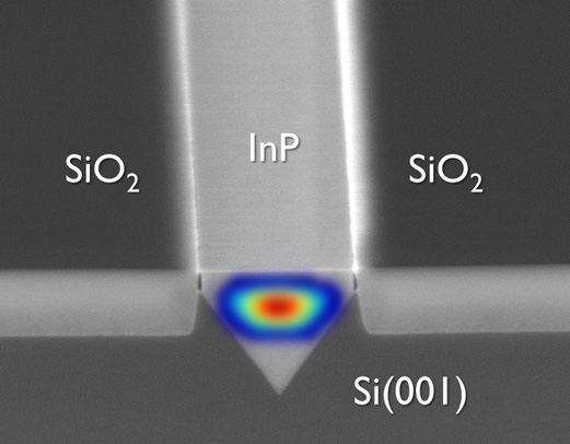 Close-up of indium phosphide deposited in the v-groove etched into the silicon wafer. Source: Ghent University, imec.
The challenge is that the amount of indium phosphide material available overall is far less, since the v-groove slots are 300 to 500 nm wide only. “We have these [narrow] slots and we have to adapt the laser design accordingly,” says Van Thourhout.
Ghent University uses the indium phosphide-deposited wafers made on imec’s 300 mm wafer pilot line and etches gratings on top to create the working lasers.
A 20mW external pump laser is used to get the array to lase, says Van Thourhout, while the output power of each laser in the array is 10 mW. The lasers operate in the 910 nm to 930 nm region.
Monolithic integration offers the best scalability once you can grow III-V [material] and do wafer-scale processing. But it is also the most challenging to implement in terms of pure physics
Future work
To get the lasers to work at 1,300 nm and 1,550 nm telecom wavelengths, another material such as indium gallium arsenide will need to be grown on top of the indium phosphide, an area Van Thourhout and his team are investigating.
However, the main challenge still remaining is to use electronic injection to drive the lasers. This requires a PIN junction to be integrated on-chip to inject carriers into the laser, and that will require adding electrical contacts which must not induce optical loss in the laser.
“That will certainly be a design challenge, getting the right doping level and so on,” says Van Thourhout. “We also have to find a way to inject current into the device without disturbing the optical field.” Only then can the reliability of laser array be determined. “That [reliability] is something that at this point is unknown but is very important for any commercial device,” he says.
Ghent University says the optically pumped lasers have not shown any breakdown and almost all the devices tested are operating well but he admits that the work remains preliminary.
Applications
Ghent University says the advent of monolithic lasers will complement existing discrete laser and hybrid techniques rather than replace them.
“The main target for monolithic is high-volume applications and more integrated designs,” says Van Thourhout. One example is optical links between a CPU and memory. Such designs that integrate optics with ICs will have to be very cheap. “The only way to make something like this very cheap is by a very high degree of integration,” says Van Thourhout.
Meanwhile, Imec has a R&D programme on optical I/O with key partners of its core CMOS programmes. Huawei has been one known partner but others include GlobalFoundries, Intel, Micron, Panasonic, Qualcomm, Samsung, SK Hynix, Sony and TSMC.
PMC unveils OTN framer for IP core and edge routers
The Meta-240G frames IP router traffic using OTN before passing the traffic to the transport network. Line-rate encryption is included on-chip to secure traffic between data centres and traffic in the cloud.
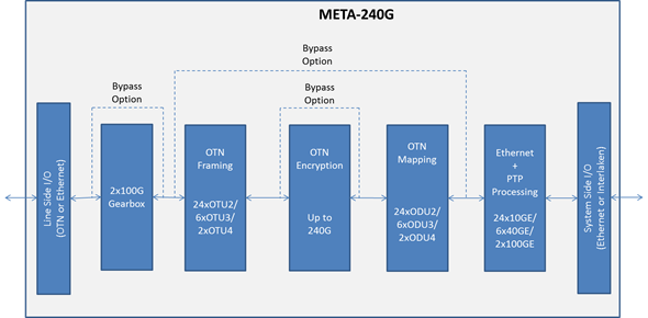 Source: PMC-Sierra
Adding OTN to a router delivers several benefits, says PMC. OTN helps identify networking faults more quickly and simplifies the monitoring and enforcement of service-level agreements. OTN also includes forward-error correction which benefits optical link performance.
Ethernet is the default router protocol interface while OTN is the dominant protocol in the transport network, says PMC. By moving OTN onto the router’s line port, the transport network extends its end-point reach to the router, says Stephen Docking, senior product line manager, communications unit at PMC. This leads to faster fault isolation and fault recovery.
“The transport network can now communicate with the router in a standard way, providing an extra level of protection that is faster than just IP layer protection,” says Docking.
OTN also supports the monitoring of error rates across the link.“By making the router part of the link, the service provider can not only monitor performance within the transport network but across the entire end-to-end link including the router,” says Docking. Such monitoring helps verify service-level agreements.
Meta-240G features
The Meta-240G is PMC’s third-generation framer for routers. The previous generation device, the 120 gigabit Meta-120G was PMC’s first to support OTU4 100 gigabit frames and was implemented in 40nm CMOS.
The Meta-240G doubles the total bandwidth: 240 gigabit facing the front panel optics and 240 gigabit interfacing to the network processor on the router’s line card. The device can thus support two 100 gigabit interfaces, six 40 gigabit interfaces and 24, 10 gigabit interfaces. “You can even have two 100 Gig and one 40 Gig, or two 100 Gig and four 10 Gig but most customers will just use 100 Gig [interfaces],” says Docking.
PMC has doubled the framer’s capacity while keeping overall power consumption fixed, in effect halving the power per port compared to its previous generation Meta-120G framer. Yet the chip also supports new features including a low-latency AES-256 encryption engine and an on-chip gearbox. The Meta-240G achieves the power savings by making the chip in 28nm CMOS and by improving the serdes design.
The gearbox function translates between 10 gigabit streams and 25 gigabit ones. Many devices use 10 gigabit serdes but to connect to a CFP2 or CFP4 100 gigabit optical modules, 25 gigabit electrical channels are required.
“Designers have had to use discrete gearbox devices [on the line card] which adds space, power and cost,” says Docking. “With the Meta-240G, the gearbox function is integrated into the device.”
Given IP traffic trends, will a 400 gigabit Meta device be needed in 2017? “It may be a bit longer - two to three years’ time - but we would need to [have such a device] to follow the existing trend,” says Docking.
Further information
PMC advances OTN with 400 Gigabit processor, click here
ECOC 2015 Review - Final Part
Part 2 - Client-side component and module developments
- The first SWDM Alliance module shown
- More companies detail CWDM4, CLR4 and PSM4 mid-reach modules
- 400 Gig datacom technologies showcased
- The CFP8 MSA for 400 Gigabit Ethernet unveiled
 The CFP MSA modules including the newest CFP8. Source: Finisar
- Lumentum and Kaiam use silicon photonics for mid-reach modules
- Finisar demonstrates a 10 km 25 Gig SFP28, and low-latency 25 Gig and 100 Gig SR4 interfaces
Shortwave wavelength-division multiplexing
Finisar demonstrated the first 100 gigabit shortwave wavelength-division multiplexing (SWDM) module at ECOC. Dubbed the SWDM4, the 100 gigabit interface supports WDM over multi-mode fibre. Finisar showed a 40 version at OFC earlier this year. “This product [the SWDM4] provides the next step in that upgrade path,” says Rafik Ward, vice president of marketing at Finisar.
The SWDM Alliance was formed in September to exploit the large amount of multi-mode fibre used by enterprises. The goal of the SWDM Alliance is to extend the use of multi-mode fibre by enabling link speeds beyond 10 gigabit.
“We believe if you can do something with multi-mode fibre, you can achieve cost points that are not achievable with single-mode fibre,” says Ward. “SWDM4 allows us to have not only low-cost optics on either end, but allows customers to reuse their installed fibre.”
The SWDM4 interface uses four 25 gigabit VCSELs operating at wavelengths sufficiently apart that cooling is not required. “By having this [wavelength] gap, you can keep to relatively low-cost components like for multiplexing and de-multiplexing,” says Ward.
The 100 Gig SWDM4 achieves 70 meters over OM3 fibre and 100 meters over OM4 fibre. SWDM can scale beyond 100 gigabit, says Ward, but the challenge with multi-mode fibre remains the tradeoff between speed and distance.
Finisar is already shipping SWDM4 alpha samples to customers.
The SWDM Alliance founding members include CommScope, Corning, Dell, Finisar, H3C, Huawei, Juniper Networks, Lumentum, and OFS.
CWDM4, CLR4 and PSM4
Oclaro detailed a 100 gigabit mid-reach QSFP28 module that supports both the CWDM4 multi-source agreement (MSA) and the CLR4 MSA. “We can support either depending on whether, on the host card, there is forward-error correction or not,” says Robert Blum, director of strategic marketing at Oclaro.
Both MSAs have a 2 km reach and use four 25 gigabit channels. However, the CWDM4 uses a more relaxed optical specification as its overall performance is complemented with forward-error correction (FEC) on the host card. The CLR4, in contrast, does not use FEC and therefore requires a more demanding optical specification.
“The requirements are significantly harder to meet for the CLR4 specification,” says Blum. By avoiding FEC, the CLR4 module benefits low-latency applications such as financial trading.
Oclaro showed its dual-MSA module achieving a 10 km reach at ECOC even though the two specifications call for 2 km only. “We have very large margins for the module compared to the specification,” says Blum, adding that customers now need to only qualify one module to meet their CWDM4 or CLR4 line card needs.
Other optical module vendors that announced support for CWDM4 in a QSFP28 module include Source Photonics, whose module is also CLR4-compliant. Kaiam is making CWDM4 and CLR4 modules using silicon photonics as part of its designs.
Lumentum also detailed its CWDM4 and the PSM4, a QSFP28 that uses a single-mode ribbon cable to deliver 100 Gig over 500 meters. Lumentum says its CWDM4 and PSM4 QSFP28 products will be available this quarter. “These 100 gigabit modules are what the hyper-scale data centre operators are clamouring for,” says Brandon Collings, CTO of Lumentum.
The question is who can ramp and support the 100 Gig deployments that are going to happen next year
Lumentum says it is using silicon photonics technology for one of its designs but has not said which. “We have both technologies [indium phosphide and silicon photonics], we use both technologies, and silicon photonics is involved with one of these [modules],” says Collings.
There is demand for both the PSM4 and CWDM4, says Lumentum. Which type a particular data centre operator chooses depends on such factors as what fibre they have or plan to deploy, whether they favour single-mode fibre pairs or ribbon cable, and if their reach requirements are beyond 500 meters.
Quite a few module companies have already sampled [100 Gig] products, says Oclaro’s Blum: “The question is who can ramp and support the 100 Gig deployments that are going to happen next year.”
Technologies for 400 gigabit
Several companies demonstrated technologies that will be needed for 400 gigabit client-side interfaces.
NeoPhotonics and chip company InPhi partnered to demonstrate the use of PAM-4 modulation to achieve 100 gigabit. “To do PAM-4, you need not only the optics but a special PAM-4 DSP,” says Ferris Lipscomb, vice president of marketing at NeoPhotonics.
The 400 Gigabit Ethernet standard under development by the IEEE 802.3bs supports several configurations using PAM-4 including a four-channel parallel single-mode fibre configuration, each at 100 gigabit that will have a 500m reach, and two 8 x 50 gigabit, for 2 km and 10 km links.
The company showcased its 4x28 Gig transmitter optical sub-assembly (TOSA) that uses a photonic integrated circuit comprising electro-absorptive modulated lasers (EMLs). Combined with InPhi’s PAM-4 chip, two channels were combined to achieve 100 gigabit. NeoPhotonics says its EMLs are also capable of supporting 56 gigabaud rates which, coupled with PAM-4, would achieve 100 gigabit single channels.
Lipscomb points out that not only are there several interfaces under development but also various optical form factors. “For 100 Gig and 400 Gig client-side data centre links, there are several competing MSA groups,” says Lipscomb. “The final winning approach has not yet emerged and NeoPhotonics wants its solution to be generic enough so that it supports this winning approach once it emerges.”
Meanwhile, Teraxion announced its silicon photonics-based modulator technology for 100 gigabit (4 x 25 Gig) and 400 gigabit datacom interfaces. “People we talk to are interested in WDM applications for short-reach links,” says Martin Guy, Teraxion’s CTO and strategic marketing.
Teraxion says a challenge using silicon photonics for WDM is supporting a broad band of wavelengths. “People use surface gratings to couple light into the silicon photonics,” says Guy. “But surface gratings have a strong wavelength-dependency over the C-band.”
Teraxion has developed an edge coupler instead which is on the same plane as the propagating light. This compares to a surface grating where light is coupled vertical to the plane.
You hear a lot about the cost of silicon photonics but one of the key advantages is the density you can achieve on the chip itself. Having many modulators in a very small footprint has value for the platform; you can make smaller and smaller transceivers.
“We can couple light efficiently with large-tolerance alignment and our approach can be used for WDM applications,” says Guy. Teraxion’s modulator array can be used for CWDM4 and CLR4 MSAs as well as optical engines for future 400 gigabit datacom systems.
“You hear a lot about the cost of silicon photonics but one of the key advantages is the density you can achieve on the chip itself,” says Guy. “Having many modulators in a very small footprint has value for the platform; you can make smaller and smaller transceivers.”
CFP8 MSA
Finisar demonstrated a 400 gigabit link that included a mock-up of the CFP8 form factor, the latest CFP MSA member being developed to support emerging standards such as 400 Gigabit Ethernet.
The 400 gigabit demonstration implemented the 400GE-SR16 multi-mode standard. A Xilinx FPGA was used to implement an Ethernet MAC and generated 16, 25 Gig channels that were fed to four CFP4 modules, each implementing a 100GBASE-SR4 but collectively acting as the equivalent of the 400GE-SR16. The 16 fibre outputs were then fed to the CFP8 prototype which performed an optical loop-back function, sending the signals back to the CFP4s and FPGA.

The CFP8 will be able to support 6.4 terabit of switching on a 1U card when used in a 2 row by 8 module configuration. The CFP8 has a similar size and power consumption profile of the CFP2. “There is still a lot of work putting an MSA together for 400 gigabit,” says Ward, adding that there is still no timeframe as to when the CFP8 MSA will be completed.
25 Gig SFP28
Finisar also announced at ECOC a 1310nm SFP28 supporting 25 gigabit Ethernet over 10 km, complementing the 850nm SFP28 short reach module it announced at OFC 2015.
Ethernet vendors are designing their next-generation series of switches that use the SFP28, says Finisar, while the IEEE is completing standardising 25 Gigabit Rthernet over copper and multi-mode fibre options.
“There hasn’t yet been a motion to standardise a long-wave interface,” says Ward. “With the demo at ECOC, we have come out with a 25 Gig long-wave interface in advance of a standard.”
Ward points out that the large-scale data centres several years ago only had 40 gigabit as a higher speed option beyond 10 gigabit. Now enterprises will also have a 25 gigabit option.
Ward points out that 25 gigabit compared to 40 Gig delivers an attractive cost-performance. Forty gigabit short-reach and long-reach interfaces are based on four channels at 10 gigabit, whereas 25 gigabit uses one laser and one photo-detector that fit in an SFP28. This compares to a QSFP for 40 Gig.
“25 Gigabit Ethernet is a very interesting interface for the next set of customers after the Web 2.0 players that are looking to migrate beyond 10 gigabit,” said Ward.
Low-latency 25 Gig SR and 100 Gig Ethernet SR4 modules
Also announced by Finisar are 25 Gigabit Ethernet SFP28 SR and 100GE QSFP28 SR4 transceivers that can operate without accompanying FEC on the host board. The transceivers achieve a 30 meter reach on OM3 fibre and 40 meters using OM4 fibre.
“Using FEC simplifies the optical link,” says Ward. “It can take the cost out of the optics by having FEC which gives you additional gain.” But some customers have requested the parts for use without FEC to reduce link latency, similar to those that choose the CLR4 MSA for mid-reach 100 Gig.
Finisar has not redesigned its modules but offering modules that have its higher performing VCSELs and photo-detectors. “Think of it as a simple screen,” says Ward.
Click here for the ECOC 2015 Review - Part 1.
Ovum Q&A: Infinera as an end-to-end systems vendor
Infinera hosted an Insight analyst day on October 6th to highlight its plans now that it has acquired metro equipment player, Transmode. Gazettabyte interviewed Ron Kline, principal analyst, intelligent networks at market research firm, Ovum, who attended the event.
Q. Infinera’s CEO Tom Fallon referred to this period as a once-in-a-decade transition as metro moves from 10 Gig to 100 Gig. The growth is attributed mainly to the uptake of cloud services and he expects this transition to last for a while. Is this Ovum’s take?
 Ron Kline, OvumRK: It is a transition but it is more about coherent technology rather than 10 Gig to 100 Gig. Coherent enables that higher-speed change which is required because of the level of bandwidth going on in the metro.
We are going to see metro change from 10 Gig to 100 Gig, much like we saw it change from 2.5 Gig to 10 Gig. Economically, it is going to be more feasible for operators to deploy 100 Gig and get more bang for their buck.
Ten years is always a good number from any transition. If you look at SONET/SDH, it began in the early 1990s and by 2000 was mainstream.
If you look at transitions, you had a ten-year time lag to get from 2.5 Gig to 10 Gig and you had another ten years for the development of 40 Gig, although that was impacted by the optical bubble and the [2008] financial crisis. But when coherent came around, you had a three-year cycle for 100 gigabit. Now you are in the same three-year cycle for 200 and 400 gigabit.
Is 100 Gig the unit of currency? I think all logic tells us it is. But I’m not sure that ends up being the story here.
If you get line systems that are truly open then optical networking becomes commodity-based transponders - the white box phenomenon - then where is the differentiation? It moves into the software realm and that becomes a much more important differentiator.
Infinera’s CEO asserted that technology differentiation has never been more important in this industry. Is this true or only for certain platforms such as for optical networking and core routers?
If you look at Infinera, you would say their chief differentiator is the PIC (photonic integrated circuit) as it has enabled them to do very well. But other players really have not tried it. Huawei does a little but only in the metro and access.
It is true that you need differentiation, particularly for something as specialised as optical networking. The edge has always gone to the company that can innovate quickest. That is how Nortel did it; they were first with 10 gigabit for long haul and dominated the market.
When you look at coherent, the edge has gone to the quickest: Ciena, Alcatel-Lucent, Huawei and to a certain extent Infinera. Then you throw in the PIC and that gives Infinera an edge.
But then, on the flip side, there is this notion of disaggregation. Nobody likes to say it but it is the commoditisation of the technology; that is certainly the way the content providers are going.
If you get line systems that are truly open then optical networking becomes commodity-based transponders - the white box phenomenon - then where is the differentiation? It moves into the software realm and that becomes a much more important differentiator.
I do think differentiation is important; it always is. But I’m not sure how long your advantage is these days.
Infinera argues that the acquisition of Transmode will triple the total available market it can address.
Infinera definitely increases its total available market. They only had an addressable market related to long haul and submarine line terminating equipment. Now this [acquisition of Transmode] really opens the door. They can do metro, access, mobile backhaul; they can do a lot of different things.
We don’t necessarily agree with the numbers, though, it more a doubling of the addressable market.
The rolling annual long-haul backbone global market (3Q 2014 to 2Q 2015) and the submarine line terminating equipment market where they play [pre-Transmode] was $5.2 billion. If you assume the total market of $14.2 billion is addressable then yes it is nearly a tripling but that includes the legacy SONET/SDH and Bandwidth Management segments which are rapidly declining. Nevertheless, Tom’s point is well-taken, adding a further $5.8 billion for the metro and access WDM markets to their total addressable market is significant.
Tom Fallon also said vendor consolidation will continue, and companies will need to have scale because of the very large amounts of R&D needed to drive differentiation. Is scale needed for a greater R&D spend to stay ahead of the competition?
When you respond to an operator’s request-for-proposal, that is where having end-to-end scale helps Infinera; being able to be a one-stop shop for the metro and long haul.
If I’m an operator, I don’t have to get products from several vendors and be the systems integrator.
Infinera announced a new platform for long haul, the XT-500, which is described as a telecom version of its data centre interconnect Cloud Xpress platform. Why do service providers want such a platform, and how does it differ from cloud Xpress?
Infinera’s DTN-X long haul platform is very high capacity and there are applications where you don’t need a such a large platform. That is one application.
The other is where you lease space [to house your equipment]. If I am going to lease space, if I have a box that is 2 RU (rack unit) high and can do 500 gigabit point-to-point and I don’t need any cross-connect, then this smaller shelf size makes a lot of sense. I’m just transporting bandwidth.
Cloud Xpress is a scaled-down product for the metro. The XT-500 is carrier-class, e.g. NEBS [Network Equipment-Building System] compliant and can span long-haul distances.
Infinera has also announced the XTC-2. What is the main purpose of this platform?
The platform is a smaller DTN-X variant to serve smaller regions. For example you can take a 500 gigabit PIC super-channel and slice it up. That enables you to do a hub-and-spoke virtual ring and drop 100 Gig wavelengths at appropriate places. The system uses the new metro PICs introduced in March. At the hub location you use an ePIC that slices up the 500G into individually routable 100G channels and at the hub location, where the XTC-2 is, you use an oPIC-100.
Does the oPIC-100 offer any advantage compared to existing100 Gig optics?
I don’t think it has a huge edge other than the differentiation you get from a PIC. In fact it might be a deterrent: you have to buy it from Infinera. It is also anti-trend, where the trend is pluggables.
But the hub and spoke architecture is innovative and it will be interesting to see what they do with the integration of PIC technology in Transmode’s gear.
Acquiring Transmode provides Infinera with an end-to-end networking portfolio? Does it still lack important elements? For example, Ciena acquired Cyan and gained its Blue Planet SDN software.
Transmode has a lot of different technologies required in the metro: mobile back-haul, synchronisation, they are also working on mobile front-hauling, and their hardware is low power.
Transmode has pretty much everything you need in these smaller platforms. But it is the software piece that they don’t have. Infinera has a strategy that says: we are not going to do this; we are going to be open and others can come in through an interface essentially and run our equipment.
That will certainly work.
But if you take a long view that says that in future technology will be commoditised, then you are in a bad spot because all the value moves to the software and you, as a company, are not investing and driving that software. So, this could be a huge problem going forward.
What are the main challenges Infinera faces?
One challenge, as mentioned, is hardware commoditisation and the issue of software.
Hardware commodity can play in Infinera’s favour. Infinera should have the lowest-cost solution given its integrated solution, so large hardware volumes is good for them. But if pluggable optics is a requirement, then they could be in trouble with this strategy
The other is keeping up with the Joneses.
I think the 500 Gig in 100 Gig channels is now not that exciting. The 500 Gig PIC is not creating as much advantage as it did before. Where is the 1.2 terabit PIC? Where is the next version that drives Infinera forward?
And is it still going to be 100 Gig? They are leading me to believe it won’t just be. Are they going to have a PIC that is 12 channels that are tunable in modulation formats to go from 100 to 200 to 400 Gig.
They need to if they want to stay competitive with everyone else because the market is moving to 200 Gig and 400 Gig. Our figures show that over 2,000 multi-rate (QPSK and 16-QAM) ports have been shipped in the last year (3Q 2014 to 2Q 2015). And now you have 8-QAM coming. Infinera’s PIC is going to have to support this.
Infinera’s edge is the PIC but if you don’t keep progressing the PIC, it is no longer an edge.
These are the challenges facing Infinera and it is not that easy to do these things.
Sckipio improves G.fast’s speed, reach and density
Sckipio has enhanced the performance of its G.fast chipset, demonstrating 1 gigabit data rates over 300 meter of telephone wire. The G.fast broadband standard has been specified for 100 meters only. The Israeli start-up has also demonstrated 2 gigabit performance by bonding two telephone wires.
 Michael Weissman
“Understand that G.fast is still immature,” says Michael Weissman, co-founder and vice president of marketing at Sckipio. “We have improved the performance of G.fast by 40 percent this summer because we haven’t had time to do the optimisation until now.”
The company also announced a 32-port distribution point unit (DPU), the aggregation unit that is fed via fibre and delivers G.fast to residences.
G.fast is part of the toolbox enabling faster and faster speeds, and fills an important role in the wireline broadband market
The 32-port design is double Sckipio’s current largest DPU design. The DPU uses eight Sckipio 4-port DP3000 distribution port chipsets, and moving to 32 lines requires more demanding processing to tackle the greater crosstalk. Vectoring uses signal processing to implement noise cancellation techniques to counter the crosstalk and is already used for VDSL2.
G.fast
“G.fast is part of the toolbox enabling faster and faster speeds, and fills an important role in the wireline broadband market,” says Julie Kunstler, principal analyst, components at market research firm, Ovum.
G.fast achieves gigabit rates over copper by expanding the usable spectrum to 106 MHz. VDSL2, the current most advanced digital subscriber line (DSL) standard, uses 17 MHz of spectrum. But operating at higher frequencies induces signal attenuation, shortening the reach. VDSL2 is deployed over 1,500 meter links typically whereas G.fast distances will likely be 300 meters or less.
Another issue is signal leakage or crosstalk between copper pairs in a cable bundle that can house tens or hundreds of copper twisted pairs. Moreover, the crosstalk becomes greater with frequency. The leakage causes each twisted pair not only to carry the signal sent but also noise, the sum of the leakage components from neighbouring pairs. Vectoring is used to restore a line's data capacity.
G.fast can be seen as the follow-on to VDSL2 but there are notable differences. Besides the wider 106 MHz spectrum, G.fast uses a different duplexing scheme. DSL uses frequency-division duplexing (FDD) where the data transmission is continuous - upstream (from the home) and downstream - but on different frequency bands or tones. In contrast, G.fast uses time-division duplexing (TDD) where all the spectrum is used to either send data or receive data.
Using TDD, the ability to adapt the upstream and downstream data ratio as well as put G.fast in a low-power mode when idle are features that DSL does not share.
“There are many attributes [of DSL] that are brought into this standard but, at a technical level, G.fast is quite fundamentally different,” says Weissman.
One Tier-1 operator has already done the bake-off and will very soon select its vendors
Status
Sckipio says all the largest operators are testing G.fast in their labs or are conducting field trials but few are going public.
Ovum stresses that telcos are pursuing a variety of broadband strategies with G.fast being just one.
Some operators have decided to deploy fibre, while others are deploying a variety of upgrade technologies - fibre-based and copper-based. G.fast can be a good fit for certain residential neighbourhood topologies, says Kunstler.
The economics of passive optical networking (PON) continues to improve. “The costs of building an optical distribution network has declined significantly, and the costs of PON equipment are reasonable,” says Kunstler, adding that skilled fibre technicians now exist in many countries and working with fibre is easier than ever before.
“Many operators see fibre as important for business services so why not just pull the fibre to support volume-residential and high average-revenue-per-user (ARPU) based business services,” she says. But in some regions, G.fast broadband speeds will be sufficient from a competitive perspective.
“One Tier-1 operator has already done the bake-off and will very soon select its vendors,” says Weissman. “Then the hard work of integrating this into their IT systems starts.”
And BT has announced that it had delivered up to 330 megabit-per-second in a trial of G.fast involving 2,000 homes, and has since announced other trials.
“BT has publically announced it can achieve 500 megabits - up and down - over 300 meters running from their cabinets,” says Weissman. “If BT moves its fibre closer to the distribution point, it will likely achieve 800 or 900 megabit rates.” Accordingly, the average customer could benefit from 500 megabit broadband from as early as 2016. And such broadband performance would be adequate for users for 8 to 10 years, he says
Meanwhile, Sckipio and other G.fast chip vendors, as well as equipment makers are working to ensure that their systems interoperate.
Sckipio has also shown G.fast running over coax cable within multi-dwelling units delivering speeds beyond 1 gigabit. “This allows telcos to compete with cable operators and go in places they have not historically gone,” says Weissman.
Standards work
The ITU-T is working to enhance the G.fast standard further using several techniques.
One is to increase the transmission power which promises to substantially improve performance. Another is to use more advanced modulation to carry extra bits per tone across the wire’s spectrum. The third approach is to double the wire's used spectrum from 106 MHz to 212 MHz.
All three approaches complicate transmission, however. Increasing the signal power and spectrum will increase crosstalk and require more vectoring, while more complex modulation will require advanced signal recovery, as will using more spectrum.
“The guys working in committee need to find the apex of these compromises,” says Weissman, adding that Sckipio believes it can generate a 50 to 70 percent improvement in data rate over a single pair using these enhancements. The standard work is likely be completed next spring.
Sckipio says it has over 30 customers for its chips that are designing over 50 G.fast systems, for the home and/ or the distribution point.
So far Sckipio has announced it is working with Calix, Adtran, Chinese original design manufacturer Cambridge Industries Group (CIG) and Zyxel, and says Sckipio products are on show in over 12 booths at the Broadband World Forum show.