
Data centres to give silicon photonics its chance
The scale of modern data centres and the volumes of transceivers they will use are going to have a significant impact on the optical industry. So claims Facebook, the social networking company.
 Katharine Schmidtke
Facebook has been vocal in outlining the optical requirements it needs for its large data centres.
The company will use duplex single-mode fibre and has chosen the 2 km mid-reach 100 gigabit CWDM4 interface to connect its equipment.
But the company remains open regarding the photonics used inside transceivers. “Facebook is agnostic to technology,“ says Katharine Schmidtke, strategic sourcing manager, optical technology at Facebook. “There are multiple technologies that meet our requirements.”
That said, Facebook says silicon photonics has characteristics that are appealing.
Silicon photonics can produce integrated designs, with all the required functions placed in one or two chips. Such designs will also be needed in volume, given that a large data centre uses hundred of thousands of optical transceivers, and that requires a high-yielding process. This is a manufacturing model the chip industry excels at, and one that silicon photonics, which uses a CMOS-compatible process, can exploit.
When you bring up a data centre, you don’t just deploy, you deploy a data centre
New business model
What data centres brings to optics is scale. Optical transceiver volumes used by data centres are growing, and growing fast, and will account for half the industry’s demand for Ethernet transceivers by 2020, according to LightCounting Market Research.
Transceivers must be designed with high-volume, low-cost manufacturing in mind from the start. This is different to what the market has done traditionally. “With the telecom industry, you step into volume in more manageable, digestible chunks,” says Schmidtke. “When you bring up a data centre, you don’t just deploy, you deploy a data centre.”
Silicon photonics has already proven it can achieve the required optical performance, says Facebook, what remains open is whether the technology can meet the manufacturing demands of the data centre. What helps its cause is that the data centre provides the volumes needed to achieve such a manufacturing maturity.
Schmidtke is upbeat about silicon photonics’ prospects.
“Why silicon photonics is attractive is integration; you are reducing the number of components and the bill of materials significantly, and that reduces cost,” she says. “Then there is all the alignment and assembly cost reductions; that is what makes this technology appealing.”
Her expectation is that the industry will demonstrate the required level of manufacturing maturity in the coming year. Then the role silicon photonics will play for this market will become clearer.
“Within a year it will be very obvious,” she says.
Verizon tips silicon photonics as a key systems enabler
Part 3: An operator view
Glenn Wellbrock is upbeat about silicon photonics’ prospects. Challenges remain, he says, but the industry is making progress. “Fundamentally, we believe silicon photonics is a real enabler,” he says. “It is the only way to get to the densities that we want.”
 Glenn Wellbrock
Wellbrock adds that indium phosphide-based photonic integrated circuits (PICs) can also achieve such densities.
But there are many potential silicon photonics suppliers because of its relatively low barrier to entry, unlike indium phosphide. "To date, Infinera has been the only real [indium phosphide] PIC company and they build only for their own platform,” says Wellbrock.
That an operator must delve into emerging photonics technologies may at first glance seem surprising. But Verizon needs to understand the issues and performance of such technologies. “If we understand what the component-level capabilities are, we can help drive that with requirements,” says Wellbrock. “We also have a better appreciation for what the system guys can and cannot do.”
Verizon can’t be an expert in the subject, he says, but it can certainly be involved. “To the point where we understand the timelines, the cost points, the value-add and the risk factors,” he says. “There are risk factors that we also want to understand, independent of what the system suppliers might tell us.”
The cost saving is real, but it is also the space savings and power saving that are just as important
All the silicon photonics players must add a laser in one form or another to the silicon substrate since silicon itself cannot lase, but pretty much all the other optical functions can be done on the silicon substrate, says Wellbrock: “The cost saving is real, but it is also the space savings and power saving that are just as important.”
The big achievement of silicon photonics, which Wellbrock describes as a breakthrough, is the getting rid of the gold boxes around the discrete optical components. “How do I get to the point where I don’t have fibre connecting all these discrete components, where the traces are built into the silicon, the modulator is built in, even the detector is built right in.” The resulting design is then easier to package. “Eventually I get to the point where the packaging is glass over the top of that.”
So what has silicon photonics demonstrated that gives Verizon confidence about its prospects?
Wellbrock points to several achievements, the first being Infinera’s PICs. Yes, he says, Infinera’s designs are indium phosphide-based and not silicon photonics, but the company makes really dense, low-power and highly reliable components.
He also cites Cisco’s silicon photonics-based CPAK 100 Gig optical modules, and Acacia, which is applying silicon photonics and its in-house DSP-ASICs to get a lower power consumption than other, high-end line-side transmitters.
Verizon believes the technology will also be used in CFP4 and QSFP28 optical modules, and at the next level of integration that avoids pluggable modules on the equipment's faceplate altogether.
But challenges remain. Scale is one issue that concerns Verizon. What makes silicon chips cheap is the fact that they are made in high volumes. “It [silicon photonics] couldn’t survive on just the 100 gigabit modules that the telecom world are buying,” says Wellbrock.
If these issues are not resolved, then indium phosphide continues to win for a long time because that is where the volumes are today
When Verizon asks the silicon photonics players about how such scale will be achieved, the response it gets is data centre interconnect. “Inside the data centre, the optics is growing so rapidly," says Wellbrock. "We can leverage that in telecom."
The other issue is device packaging, for silicon photonics and for indium phosphide. It is ok making a silicon-photonics die cheaply but unless the packaging costs can be reduced, the overall cost saving is lost. ”How to make it reliable and mainstream so that everyone is using the same packaging to get cost down,” says Wellbrock.
All these issues - volumes, packaging, increasing the number of applications a single part can be applied to - need to be resolved and almost simultaneously. Otherwise, the technology will not realise its full potential and the start-ups will dwindle before the problems are fixed.
“If these issues are not resolved, then indium phosphide continues to win for a long time because that is where the volumes are today,” he says.
Verizon, however, is optimistic. “We are making enough progress here to where it should all pan out,” says Wellbrock.
The quiet period of silicon photonics
Michael Hochberg discusses his book on silicon photonics and the status of the technology. Hochberg is director of R&D at Coriant's Advanced Technology Group. Previously he has been an Associate Professor at the University of Delaware and at the National University of Singapore. He was also a director at the Optoelectronic Systems Integration in Silicon (OpSIS) foundry, and was a co-founder of silicon photonics start-up, Luxtera.
Part 2: An R&D perspective
If you are going to write a book on silicon photonics, you might as well make it different. That is the goal of Michael Hochberg and co-author Lukas Chrostowski, who have published a book on the topic.
 Michael HochbergHochberg says there is no shortage of excellent theoretical textbooks and titles that survey the latest silicon photonics research. Instead, the authors set themselves the goal of creating a design manual to help spur a new generation of designers.
The book aims to provide designers with all the necessary tools and know-how to develop silicon photonics circuits without needing to be specialists in optics.
“One of the limiting factors in terms of the growth and success of the field is how quickly can we breed up more and more designers,” says Hochberg.
The book - Silicon Photonics Design: From Devices to Systems - starts by exploring the main silicon photonics building blocks, from optical waveguides and grating couplers to modulators, photo-detectors and lasers. The book then addresses putting the parts together, with chapters on tools, fabrication, testing and packaging before finishing with system design examples.
The numerical tools used in the book are mostly based on the finite-difference time-domain method, what the authors describe as the typical workhorse in silicon photonics design. Hochberg admits that the systems software tools, in contrast, are less mature: “It is a moving target that will change year to year.”
Myths
Hochberg is also a co-author of a Nature Photonics’ paper, published in 2012, that debunks some of the myths regarding silicon photonics. “We wrote the myths paper after seeing an upswing in the ratio of hype-to-results going on,” says Hochberg.
He says part of the problem was that people were claiming silicon photonics was going to solve problems that it was plainly unsuited to address, for example integrating photonics with cutting-edge ultra-scale sub-micron electronics, for instance at 16 nm and 28 nm nodes. “That is not a practical solution for any near term problem,” says Hochberg.
More recent events, such as Intel’s announcement in February that it is delaying the commercial introduction of its silicon photonics products, highlights how bringing the technology to market is a significant engineering challenge. Instead, we are in a quiet period for silicon photonics, he says. Companies are getting into serious product mode, where they stop publishing and start focussing on building a product.
Moreover, these products - what he refers to as second-generation silicon photonics designs - are increasingly sophisticated with more functions or channels placed on the chip. “It is the standard story of almost any technology in silicon,” he says. “Silicon wins when you can do more stuff on a single chip.”
Silicon photonics and III-V
Hochberg stresses that while it is an understandable desire, it is very hard to compare the performance of silicon photonics as a whole with traditional optical components using III-V compounds. The issue being that silicon photonics comprises many different platforms where designers have made tradeoffs. The same applies to III-V compounds where there are hundreds of processes aimed at thousands of different products. “It is very hard to compare them in a generic way,” he says.
“The great advantage silicon photonics gives you is access to first-rate fabrication infrastructure,” says Hochberg. Silicon photonics offers 8- and 12-inch wafers, high volume foundries, high process control, the ability to ramp to high volumes and achieve high yields of complex-structure designs with hundreds, even thousands of components on-chip.
In contrast, III-V materials such as indium phosphide and gallium arsenide offer higher mobilities - electrons and holes move faster - and, unlike silicon, can straightforwardly emit light.
“The downside is that III-V foundries use technology processes that silicon stopped using 20 to 30 years ago,” says Hochberg. Wafers that are 2-, 3- or 4-inch in diameter, lithography that is ten times coarser than is used for silicon, process controls that are less advanced, and less automation.
If you are going to design a complex chip with lots of different components that require a predictable relationship with each other, this is where silicon tends to beat III-Vs, he says.
But the claim of large silicon wafers and huge volumes is what silicon photonics proponents have been promoting for years, and which has fed some of the false expectation associated with the emerging technology, says one industry analyst.
Hochberg counters by highlighting two trends that play in silicon photonics’ favour.
One is the well-known one of optics slowly replacing copper. This has been going on for 40 to 50 years, he says, in long haul, then in metro and now linking equipment in the data centre. “This will continue for shorter and shorter distances and then, at some point, stop,” he says. That said, Hochberg stresses that there are other applications for silicon photonics besides data communications.
“Just because you run out of opportunities at shorter and shorter reach at some point in the distant future, doesn't mean that the field collapses,” he says. “There's a lot of other cool stuff being done in silicon photonics these days with serious commercial potential.” Example applications include medical and remote sensing.
Once you can do something in silicon and do it adequately well, it tends to displace everything else from the majority of the market
The second trend he highlights is that silicon ends up dominating fields, not necessarily because it is the best choice in terms of performance but because it ends up being so cheap in scale. “Once you can do something in silicon and do it adequately well, it tends to displace everything else from the majority of the market.”
There are up-front costs of getting silicon photonics into a CMOS fab so companies have to be judicious in choosing the applications they tackle. “But once the infrastructure gets going to make a new application, the speed with which the industry can scale is just mind-blowing,” he said.
At Coriant, Hochberg leads a team that is doing advanced R&D. “We are doing advanced research with the goal to develop new technology that may eventually make its way into product.”
Does that include silicon photonics? “There is certainly an interest in silicon photonics; it is one of the things we are exploring,” says Hochberg.
Further reading:
Book: Michael Hochberg and Lukas Chrostowski, Silicon Photonics Design: From Devices to Systems, Cambridge University Press, 2015
Paper: Myths and rumours of silicon photonics, Nature Photonics, Vol 6, April 2012.
Silicon photonics: "The excitement has gone"
The opinion of industry analysts regarding silicon photonics is mixed at best. More silicon photonics products are shipping but challenges remain.
Part 1: An analyst perspective
"The excitement has gone,” says Vladimir Kozlov, CEO of LightCounting Market Research. “Now it is the long hard work to deliver products.”
 Dale Murray, LightCounting
However, he is less concerned about recent setbacks and slippages for companies such as Intel that are developing silicon photonics products. This is to be expected, he says, as happens with all emerging technologies.
Mark Lutkowitz, principal at consultancy fibeReality, is more circumspect. “As a general rule, the more that reality sets in, the less impressive silicon photonics gets to be,” he says. “The physics is just hard; light is not naturally inclined to work on the silicon the way electronics does.”
LightCounting, which tracks optical component and modules, says silicon photonics product shipments in volume are happening. The market research firm cites Cisco’s CPAK transceivers, and 40 gigabit PSM4 modules shipping in excess of 100,000 units as examples. Six companies now offer 40 gigabit PSM4 products with Luxtera, a silicon photonics player, having a healthy start on the other five.
Indium phosphide and other technologies will not step back and give silicon photonics a free ride
LightCounting also cites Acacia with its silicon photonics-based low-power 100 and 400 gigabit coherent modules. “At OFC, Acacia made a fairly compelling case, but how much of its modules’ optical performance is down to silicon photonics and how much is down to its advanced coherent DSP chip is unclear,” says Dale Murray, principal analyst at LightCounting. Silicon photonics has not shown itself to be the overwhelming solution for metro/ regional and long-haul networks to date but that could change, he says.
Another trend LightCounting notes is how PAM-4 modulation is becoming adopted within standards. PAM-4 modulates two bits of data per symbol and has been adopted for the emerging 400 Gigabit Ethernet standard. Silicon photonics modulators work really well with PAM-4 and getting it into standards benefits the technology, says LightCounting. “All standards were developed around indium phosphide and gallium arsenide technologies until now,” says Kozlov.
You would be hard pressed to find a lot of OEMs or systems integrators that talk about silicon photonics and what impact it is going to have
Silicon photonics has been tainted due to the amount of hype it has received in recent years, says Murray. Especially the claim that optical products made in a CMOS fabrication plant will be significantly cheaper compared to traditional III-V-based optical components.
First, Murray highlights that no CMOS production line can make photonic devices without adaptation. “And how many wafers starts are there for the whole industry? How much does a [CMOS] wafer cost?” he says.
“You would be hard pressed to find a lot of OEMs or systems integrators that talk about silicon photonics and what impact it is going to have,” says Lutkowitz. “To me, that has always said everything.”
![]() Mark Lutkowitz, fibeReality LightCounting highlights heterogeneous integration as one promising avenue for silicon photonics. Heterogeneous integration involves bonding III-V and silicon wafers before processing the two.
Mark Lutkowitz, fibeReality LightCounting highlights heterogeneous integration as one promising avenue for silicon photonics. Heterogeneous integration involves bonding III-V and silicon wafers before processing the two.
This hybrid approach uses the III-V materials for the active components while benefitting from silicon’s larger (300 mm) wafer sizes and advanced manufacturing techniques.
Such an approach avoids the need to attach and align an external discrete laser. “If that can be integrated into a WDM design, then you have got the potential to realise the dream of silicon photonics,” says Murray. “But it’s not quite there yet.”
This poses a real challenge for silicon photonics: it will only achieve low cost if there are sufficient volumes, but without such volumes it will not achieve a cost differential
Murray says over 30 vendors now make modules at 40 gigabit and above: “There are numerous module types and more are being added all the time.” Then there is silicon photonics which has its own product pie split. This poses a real challenge for silicon photonics: it will only achieve low cost if there are sufficient volumes, but without such volumes it will not achieve a cost differential.
“Indium phosphide and other technologies will not step back and give silicon photonics a free ride, and are going to fight it,” says Kozlov. Nor is it just VCSELs that are made in high volumes.
LightCounting expects over 100 million indium phosphide transceivers to ship this year. Many of these transceivers use distributed feedback (DFB) lasers and many are at 10 gigabit and are inexpensive, says Kozlov.
For FTTx and GPON, bi-directional optical subassemblies (BOSAs) now cost $9, he says: “How much lower cost can you get?”
Europe gets its first TWDM-PON field trial
Vodafone is conducting what is claimed to be the first European field trial of a multi-wavelength passive optical networking system using access equipment from Alcatel-Lucent.
 Source: Alcatel-Lucent
The time- and wavelength-division multiplexed passive optical network (TWDM-PON) technology being used is a next-generation access scheme that follows on from 10 gigabit GPON (XG-PON1) and 10 gigabit EPON.
“There appears to be much more 'real' interest in TWDM-PON than in 10G GPON,” says Julie Kunstler, principal analyst, components at Ovum.
The TWDM-PON standard is close to completion in the Full Service Access Network (FSAN) Group and ITU and supports up to eight wavelengths, each capable of 10 gigabit symmetrical or 10/ 2.5 gigabit asymmetrical speeds.
“You can start building hardware solutions that are fully [standard] compliant,” says Stefaan Vanhastel, director of fixed access marketing at Alcatel-Lucent.
TWDM-PON’s support for additional functionality such as dynamic wavelength management, whereby subscribers could be moved between wavelengths, is still being standardised.
The combination of time and wavelength division multiplexing, allows TWDM-PON to support multiple PONs, each sharing its capacity among 16, 32, 64 or even 128 end points depending on the operator’s chosen split ratio.
There appears to be much more 'real' interest in TWDM PON than in 10G GPON
Alcatel-Lucent first detailed its TWDM-PON technology last year. The system vendor introduced a four-wavelength TWDM-PON based on a 4-port line-card, each port supporting a 10 gigabit PON. The line card is used with Alcatel-Lucent’s 7360 Intelligent Services Access Manager FX platform, and supports fixed and tunable SFP optical modules.
“Several vendors also offer the possibility to use fixed wavelength - XG-PON1 or 10G EPON optics," says Vanhastel. "This reduces the initial cost of a TWDM-PON deployment while allowing you to add tunable optics later."
Operators can thus start with a 10 gigabit PON using fixed-wavelength optics and move to TWDM-PON and tunable modules as their capacity needs grow. “You won’t have to swap out legacy XG-PON1 hardware two years from now,” says Vanhastel.
Alcatel-Lucent has been involved in 16 customer TWDM-PON trials overall, half in Asia Pacific and the rest split between North America and EMEA. Besides Vodafone, Alcatel-Lucent has named two other TWDM-PON triallists: Telefonica and Energia, an energy utility in Japan.
You won’t have to swap out legacy XG-PON1 hardware two years from now
Vanhastel says the company has been surprised that operators are also eyeing the technology for residential access. The high capacity and relative expense of tunable optics made the vendor think that early demand would be for business services and mobile backhaul only.
 Source: Gazettabyte
There are several reasons for the operator interest in TWDM-PON, says Vanhastel. One is its ample bandwidth - 40 gigabit symmetrical in a four-wavelength implementation - and that wavelengths can be assigned to different aggregation tasks such as backhaul, business and residential. Operators can also pay for wavelengths as needed.
TWDM-PON also allows wavelengths to be shared between operators as part of wholesale agreements. Operators deploying TWDM-PON can lease a wavelength to each other in their respective regions.
Vodafone, for example, is building its own fibre network but is also expanding its overall fixed broadband coverage by developing wholesale agreements across Europe. Vodafone's European broadband network covers 62 million households: 26 million premises covered with its own network and 36 million through wholesale agreements.
First operator TWDM-PON pilot deployments will occur in 2016, says Alcatel-Lucent.
Further reading:
White Paper: TWDM PON is on the horizon: facilitating fast FTTx network monetization, click here
Silicon photonics economics set to benefit III-V photonics
Silicon photonics promises to deliver cheaper optical components using equipment, processes and fabrication plants paid for by the chip industry. Now, it turns out, traditional optical component players using indium phosphide and gallium arsenide can benefit from similar economies, thanks to the wireless IC chip industry.
 Valery TolstikhinSilicon photonics did a good thing; it turned the interest of the photonics industry to the operational ways of silicon
So argues Valery Tolstikhin, head of a design consultancy, Intengent, and former founder and CTO of Canadian start-up OneChip Photonics. The expectations for silicon photonics may yet to be fulfilled, says Tolstikhin, but what the technology has done is spark interest in the economics of component making. And when it comes to chip economics, volumes count.
“For III-V photonics - indium phosphide and related materials - you have all kinds of solutions, designs and processes, but all are boutique,” says Tolstikhin. “They are not commercialised in a proper way and there is no industrial scale.” The reason for this is simple: optical components is a low-volume industry.
This is what Tolstikhin seeks to address by piggybacking on high-volume indium phosphide and gallium arsenide fabrication plants that make monolithic microwave integrated circuits (MMICs) for wireless.
“To take photonics out of boutique fabs, you need to do some standardisation and move to a fabless model, then you can load the fabs day and night with wafers,” says Tolstikhin. “That is the only way to make a process mature, reproducible and reliable.”
Tolstikhin has spent the last decade pursuing this approach. “The idea is to use something available in indium phosphide which is relatively close to a pure-play foundry.” A pure-play foundry is a fab that makes chips but does not design, market or sell them as its own products.
Tolstikhin’s first involvement was at start-up OneChip Photonics which developed an indium-phosphide platform that used a variety of photonic devices to make photonic integrated circuits (PICs), based on a commercial MMIC process.
The issue with III-V integrated photonics is that to implement different functions - a passive waveguide and a laser, for example - different materials are needed. “What makes a low-loss passive waveguide, does not work for the laser,” says Tolstikhin.
To overcome this, the wafer is repeatedly etched in certain areas, to remove unwanted material, and new layers grown instead with the required material, a process known as selective-area etch and regrowth. This is a complicated and relatively low-yield process that is custom to companies and their fabs, he says: “This is how all commercial lasers and PICs are made.”
In contrast, MMICs using indium phosphide do not need regrowth, simplifying the process considerably. To use a MMIC fab for an optical design, however, it must be developed in a way that avoids the need for regrowth stages.
“At OneChip we believe we did the first commercial laser - not just the laser but the PIC with it - regrowth-free,” says Tolstikhin. “It was made in a MMIC fab, that is the key.”
“To take photonics out of boutique fabs, you need to do some standardisation and move to a fabless model, then you can load the fabs day and night with wafers”
Wafer economics
To understand the relative economics, Tolstikhin compares the number of wafers - wafer starts - processed in silicon, indium phosphide and gallium arsenide.
One large TSMC fab has 400,000 12-inch CMOS wafer starts a year whereas globally the figure is equivalent to some 70 million such wafers a year. For MMICs, one fab Tolstikhin works with has 15,000 4-inch indium phosphide wafer starts a year whereas a large optical component company uses just a couple of thousand 3-inch indium phosphide wafers a year.
“In photonics, the [global] volumes – even for components going into the most massive markets like PON and the data centre interconnects – are still very low,” says Tolstikhin.
Gallium arsenide is somewhere in between: Win’s fab in Taiwan, which makes power amplifiers for wireless and other MMICs, has 250,000 6-inch wafers starts a year, while TriQuint’s fab in USA, with similar product line in wireless, totals 150,000 6-inch wafer starts a year.
Such volumes are not negligible and exceed all the needs of photonics, he says, enabling photonics to make claims similar to those trumpeted for silicon photonics: a mature process with a well-established quality system and, with its volumes, delivers better economics.
Moreover, if applications that currently are based on indium phosphide could be transferred to gallium arsenide, that would give an order of magnitude economies of scale, says Tolstikhin: “One example is mid-reach single-mode optical interconnects with an operating wavelength around 1060 nm, with gallium arsenide used for the transmitter, receiver and transceiver PICs”.
And while the scale of III-V semiconductor manufacturing may still be much lower than CMOS, the up-front cost involved in using a III-V fab is also much less.
Using III-V semiconductors for analogue electronics like the laser /modulator drivers or the trans-impedance amplifier also delivers a speed advantage: heterojunction bipolar transistors (HBTs) in indium phosphide have been demonstrated working at up to 400 GHz, and these, being vertical devices, do not have their speed scaled with lithography. In contrast, CMOS analog electronics is much slower and its device speed is scalable with lithography resolution. A 130 nm CMOS process, the starting point for silicon photonics, cannot support optical components with bit rates beyond 10 Gbps.
Design house
Intengent, Tolstikhin’s company, acts as a bridge between OEMs building optical components and sub-systems and the III-V foundries making photonic chips for them.
He compares Intengent to what application-specific IC (ASIC) companies used to do for the electronic chip industry. Intengent works with the OEM to specify and design the photonic chip based on its system application and then works with the fab to develop and turn the chip into a product by meeting its design rules and process capabilities.
“The aim is that you can go and design within existing fabs and processes something that meets the customer’s application and requirements,” he says.
Tolstikhin is also working with ELPHiC, a Canadian start-up that is raising funding to develop single-mode mid-board optics. The indium-phosphide design combines analogue electronic circuitry with the photonics.
“It appears the best way [to do mid-board optics] is based on electronic and photonic integration onto one substrate and indium phosphide is a natural choice for such a substrate,” he says.
Tolstikhin makes clear he is not against silicon photonics. “It did a good thing; it turned the interest of the photonics industry to the operational ways of silicon: standardised processes, pure-play foundries, device designs separate from the semiconductor physics, and circuit designs separate from the wafer processing.”
As a result, something similar is now being pursued in III-V photonics.
IBM demos a 100 Gigabit silicon photonics transceiver
“It is a demonstration vehicle illustrating the complex design capabilities of the technology and the functionality of the optical and electrical components,” says Will Green, manager of IBM’s silicon integrated nano-photonics group.
 Will Green
IBM has been developing silicon photonics technology for over a decade, starting with building-block optical functions based on silicon, to its current monolithic system-on-chip technology that includes design tools, testing and packaging technologies.
Now this technology is nearing commercialisation.
“We do plan to have the technology available for use within IBM’s systems but also within the larger market; large-volume applications such as the data centre and hyper-scale data centres in particular,” says Green.
IBM is already working with companies developing their own optical component designs using its technology and design tools. “These are tools that circuit designers are familiar with, such that they do not need to have an in-depth knowledge of photonics in order to build, for example, an optical transceiver,” says Green.
We do plan to have the technology available for use within IBM’s systems but also within the larger market
100 gig demonstrator
IBM refers to its silicon photonics technology as CMOS-integrated nano-photonics. CMOS-integrated refers to the technology’s monolithic nature that combines CMOS electronics with photonics on one substrate. Nano-photonics highlights the dimensions of the feature sizes used.
IBM is rare among the silicon photonics community in combining electronics and photonics on one chip; other players implement photonics and electronics on separate dies before combining the two. What is not included is the laser which is externally attached using fibre.
The platform supports 25 gigabit speeds as well as wavelength division multiplexing. Originally, IBM started with 90 nm CMOS using bulk silicon before transferring to a silicon-on-insulator (SOI) substrate. An SOI wafer is ideal for creating optical waveguides that confine light using the large refractive index difference between silicon and silicon dioxide. However, to make the electrical devices run at 25 gigabit, the resulting transistor gate length ended up being closer to a 65 nm CMOS process.
 Source: IBM Corporation.
IBM's optical waveguides are sub-micron, having dimensions of a few hundred nanometers. This is the middle ground, says Green, trading off the density of smaller-dimensioned waveguides with larger, micron-plus ones that deliver low propagation loss.
Also used are sub-wavelength optical 'metamaterial' structures that transition between the refractive index of the fibre and that of the optical waveguide to achieve a good match between the two. “These very tiny sub-wavelength structures are made using lithography near the limits of what is available,” says Green. “We are engineering the optical properties of the waveguide in order to achieve a low insertion loss when bringing the fibre onto the chip.” The single mode fibre to the chip is attached using passive alignment.
The 100 gigabit transceiver demonstrator uses four 25 gigabit coarse wavelengths around 1310 nm. The technology is suited to implement the CWDM4 MSA.
The whole technology is available to be commercialised by any chip manufacturer
“We are working with four wavelengths today but in the same way as telecom uses many wavelengths, we can follow a similar path,” says Green.
The chip design features transmitter electronics - a series of amplifiers that boost the voltage to drive the Mach-Zehnder Interferometer modulators - and a multiplexer to combine the four wavelengths onto the fibre while the receiver circuitry includes a demultiplexer, four photo-detectors and trans-impedance amplifiers and limiting amplifiers, says Green. What is lacking to make the 100 gigabit transceiver functional is a micro-controller, feedback loops to control the temperature of key circuits, and the circuitry to interface to standard electrical input/ output.
Green highlights how the bill of materials of a chip is only a fraction of the total cost since assembly and testing must also be included.
“We reduce the cost of assembly through automated passive optical alignment and the introduction of custom structures onto the wafer,” he says. “We believe we can make an impact on the cost structure of the optical transceiver and where this technology needs to be to access the data centre.” IBM has also developed a way to test the transceiver chips at the wafer level.
Green admits that its CMOS-integrated nanophotonics process will not scale beyond 25 gigabit as the 90-65 nm CMOS is not able to implement faster serial rates. But IBM has already shown an optical implementation of the PAM-4 modulation scheme that doubles a link's rate to 50 gigabit.
Meanwhile, IBM’s process design kit (PDK) is already with customers. A PDK includes documents and data files that describe the fabrication process and enable a user to complete a design. A PDK includes a fab’s process parameters, mask layout instructions, and the library of silicon photonics components; grating couplers, waveguides, modulators and the like [1].
“They [customers] have used the design kit provided by IBM but have built their own designs,” says Green. “And now they are testing hardware.”
IBM is keen that its silicon photonics technology will be licensed and used by circuit design houses. "Houses that bring their own IP [intellectual property], use the enablement tools and manufacture at a site that is licensing the technology from IBM,” says Green. "The whole technology is available to be commercialised by any chip manufacturer.”
Reference
[1] Silicon Photonics Design: From Devices to Systems, Lukas Chrostowski and Michael Hochberg, Cambridge University Press, 2015. Click here
Altera’s 30 billion transistor FPGA
- The Stratix 10 features a routing architecture that doubles overall clock speed and core performance
- The programmable family supports the co-packaging of transceiver chips to enable custom FPGAs
- The Stratix 10 family supports up to 5.5 million logic elements
- Enhanced security features stop designs from being copied or tampered with
Altera has detailed its most powerful FPGA family to date. Two variants of the Stratix 10 family have been announced: 10 FPGAs and 10 system-on-chip (SoC) devices that include a quad-core 64-bit architecture Cortex-A53 ARM processor alongside the programmable logic. The ARM processor can be clocked at up to 1.5 GHz.
The Stratix 10 family is implemented using Intel’s 14nm FinFET process and supports up to 5.5 million logic elements. The largest device in Altera’s 20nm Arria family of FPGAs has 1.15 million logic elements, equating to 6.4 billion transistors. “Extrapolating, this gives a figure of some 30 billion transistors for the Stratix 10,” says Craig Davis, senior product marketing manager at Altera.
 Altera's HyperFlex routing architecture. Shown (pointed to by the blue arrow) are the HyperFlex registers that sit at the junction of the interconnect traces. Also shown are the adaptive logic module blocks. Source: Altera.
The FPGA family uses a routing fabric, dubbed HyperFlex, to connect the logic blocks. HyperFlex is claimed to double the clock speed compared to designs implemented using Altera’s Stratix V devices, to achieve gigahertz rates. “Having that high level of performance allows us to get to 400 gigabit and one terabit OTN (Optical Transport Network) systems,” says Davies.
The FPGA company detailed the Stratix 10 a week after Intel announced its intention to acquire Altera for US $16.7 billion.
Altera is also introducing with the FPGA family what it refers to as heterogeneous 3D system packaging and integration. The technology enables a designer to customise the FPGA’s transceivers by co-packaging separate transceiver integrated circuits (ICs) alongside the FPGA.
Different line-rate transceivers can be supported to meet a design's requirements: 10, 28 or 56 gigabit-per-second (Gbps), for example. It also allows different protocols such as PCI Express (PCIe), and different modulation formats including optical interfaces. Altera has already demonstrated a prototype FPGA co-packaged with optical interfaces, while Intel is developing silicon photonics technology.
HyperFlex routing
The maximum speed an FPGA design can be clocked is determined by the speed of its logic and the time it takes to move data from one part of the chip to another. Increasingly, it is the routing fabric rather than the logic itself that dictates the total delay, says Davis.
This has led the designers of the Stratix 10 to develop the HyperFlex architecture that adds a register at each junction of the lines interconnecting the logic elements.
Altera first tackled routing delay a decade ago by redesigning the FPGA’s logic building block. Altera went from a 4-input look-up table logic building block to a more powerful 8-input one that includes output registers. Using the more complex logic element - the adaptive logic module (ALM) - simplifies the overall routing. “You are essentially removing one layer of routing from your system,” says Davies.
When an FPGA is programmed, the file is presented that dictates how the wires and hence the device’s logic are connected. The refinement with HyperFlex is that there are now registers at those locations where the switching between the traces occurs. A register can either be bypassed or used.
“It allows us to put the registers anywhere in the design, essentially placing them in an optimum place for a given route across the FPGA,” says Davies. The number of hyper-registers in the device's routing outnumber the standard registers in the ALM blocks by a factor of ten.
Using the registers, designers can introduce data pipelining to reduce overall delay and it is this pipelining, combined with the advanced 14nm CMOS process, that allows a design to run at gigahertz rates.
“We have made the registers small but they add one or two percent to the total die area, but in return it gives us the ability to go to twice the performance,” says Davies. “That is a good trade-off.
The biggest change getting HyperFlex to work has been with the software tools, says Davies. HyperFlex and the associated tools has taken over three years to develop.
“This is a fundamental change,” says Davies. “It [HyperFlex] is relatively simple but it is key; and it is this that allows customers to get to this doubling of core performance.”
The examples cited by Altera certainly suggest significant improvements in speed, density, power dissipation, but I want to see that in real-world designs
Loring Wirbel, The Linley Group
Applications
Altera says that over 100 customer designs have now been processed using the Stratix 10 development tools.
It cites as an example a current 400 gigabit design implemented using a Stratix V FPGA that requires a bus 1024-bits wide, clocked at 390MHz. The wide bus consumes considerable chip area and routing it to avoid congestion is non-trivial.
Porting the design to a Stratix 10 enables the bus to be clocked at 781MHz such that the bus width can be halved to 512 bits. “It reduces congestion, makes it easier to do timing closure and ship the design,” says Davies. “This is why we think Stratix 10 is so important for high-performance applications like OTN and data centres.” Timing closure refers to the tricky part of a design where the engineer may have to iterate to ensure that a design meets all the timing requirements.
For another, data centre design, a Stratix 10 device can replace five Stratix V ICs on one card. The five FPGAs are clocked at 250MHz, run PCIe Gen2 x8 interfaces and DDR3 x72 memory clocked at 800MHz. Overall the power consumed is 120W. Using one Stratix 10 chip clocked at 500MHz, faster PCIe Gen3 x8 can be supported as can a wider DDR3 x144 memory clocked at 1.2GHz, with only 44W consumed.
Loring Wirbel, senior analyst at The Linley Group, says that Altera’s insertion of pipelined registers to cut average trace lengths is unique.
“The more important question is, can the hyper-register topology regularly gain the type of advantages claimed?” says Wirbel. “The examples cited by Altera certainly suggest significant improvements in speed, density, power dissipation, but I want to see that in real-world designs.”
We are also looking at optical transceivers directly connected to the FPGA
Craig Davies, Altera
Connectivity tiles
Altera recognises that future FPGAs will support a variety of transceiver types. Not only are there different line speeds to be supported but also different modulation schemes. “You can’t build one transceiver that fits all of these requirements and even if you could, it would not be an optimised design,” says Davies.
Instead, Altera is exploiting Intel’s embedded multi-die interconnect bridge (EMIB) technology to interface the FPGA and transceivers, dubbed connectivity tiles. The bridge technology is embedded into the chip’s substrate and enables dense interconnect between the core FPGA and the transceiver IC.
Intel claims fewer wafer processing steps are required to make the EMIB compared to other 2.5D interposer processes. An interposer is an electrical design that provides connectivity. “This is a very simple ball-grid sort of interposer, nothing like the Xilinx interposer,” says Wirbel. “But it is lower cost and not intended for the wide range of applications that more advanced interposers use.”
Using this approach, a customer can add to their design the desired interface, including optical interfaces as well as electrical ones. “We are also looking at optical transceivers directly connected to the FPGA,” says Davies.
Wirbel says such links would simplify interfacing to OTN mappers, and data centre designs that use optical links between racks and for the top-of-rack switch.
“Intel wants to see a lot more use of optics directly on the server CPU board, something that the COBO Alliance agrees with in part, and they may steer the on-chip TOSA/ ROSA (transmitter and receiver optical sub-assembly) toward intra-board applications,” he says.
But this is more into the future. “It's fine if Intel wants to pursue those things, but it should not neglect common MSAs for OTN and Ethernet applications of a more traditional sort,” says Wirbel.
The benefit of the system-in-package integration is that different FPGAs can be built without having to create a new expensive mask set each time. “You can build a modular lego-block FPGA and all that it has different is the packaged substrate,” says Davies.
Security and software
Stratix 10 also features security features to protect companies’ intellectual property from being copied or manipulated.
The FPGA features security hardware that protects circuitry from being tampered with; the bitstream that is loaded to configure the FPGA must be decrypted first.
The FPGA is also split into sectors such that parts of the device can have different degrees of security. The sectoring is useful for cloud-computing applications where the FPGA is used as an accelerator to the server host processor. As a result, different customers’ applications can be run in separate sectors of the FPGA to ensure that they are protected from each other.
The security hardware also allows features to be included in a design that the customer can unlock and pay for once needed. For example, a telecom platform could be upgraded to 100 Gigabit while the existing 40 Gig live network traffic runs unaffected in a separate sector.
Altera has upgraded its FPGA software tools in anticipation of the Stratix 10. Features include a hierarchical design flow to simplify the partitioning of a design project across a team of engineers, and the ability to use cloud computing to speed up design compilation time.
What applications will require such advanced FPGAs, and which customers will be willing to pay a premium price for? Wirbel says the top applications will remain communications.
“The emergence of new 400 Gig OTN transport platforms, and the emergence of all kinds of new routers and switches with 400 Gig interfaces, will keep a 40 percent communication base for FPGAs overall solid at Altera,” he says.
Wirbel also expects server accelerator boards where FPGA-based accelerators are used for such applications as financial trading and physics simulation will also be an important market. “But Intel must consider the accelerator board market as an ideal place for Stratix 10 on its own, and not merely as a vehicle for promoting a future Xeon-plus-FPGA hybrid,” he says.
Altera will have engineering samples of the Stratix 10 towards the end of 2015, before being shipped to customers.
ADVA's 100 Terabit data centre interconnect platform
- The FSP 3000 CloudConnect comes in several configurations
- The data centre interconnect platform scales to 100 terabits of throughput
- The chassis use a thin 0.5 RU QuadFlex card with up to 400 Gig transport capacity
- The optical line system has been designed to be open and programmable
ADVA Optical Networking has unveiled its FSP 3000 CloudConnect, a data centre interconnect product designed to cater for the needs of the different data centre players. The company has developed several sized platforms to address the workloads and bandwidth needs of data centre operators such as Internet content providers, communications service providers, enterprises, cloud and colocation players.
Certain Internet content providers want to scale the performance of their computing clusters across their data centres. A cluster is a grouping of distributed computing comprising a defined number of virtual machines and processor cores (see Clusters, pods and recipes explained, bottom). Yet there are also data centre operators that only need to share limited data between their sites.
ADVA Optical Networking highlights two internet content providers - Google and Microsoft with its Azure cloud computing and services platform - that want their distributed clusters to act as one giant global cluster.
“The performance of the combined clusters is proportional to the bandwidth of the interconnect,” says Jim Theodoras, senior director, technical marketing at ADVA optical Networking. “No matter how many CPU cores or servers, you are now limited by the interconnect bandwidth.”
ADVA Optical Networking cites a Google study that involved running an application on different cluster configurations, starting with a single cluster; then two, side-by-side; two clusters in separate buildings through to clusters across continents. Google claimed the distributed clusters only performed at 20 percent capacity due to the limited interconnect bandwidth. “The reason you are hearing these ridiculous amounts of connectivity, in the hundreds of terabits, is only for those customers that want their clusters to behave as a global cluster,” says Theodoras.
Yet other internet content providers have far more modest interconnect demands. ADVA cites one, as large as the two global cluster players, that wants only 1.2 terabit-per-second (Tbps) between its sites. “It is normal duplication/ replication between sites,” says Theodoras. “They want each campus to run as a cluster but they don’t want their networks to behave as a global cluster.”
FSP 3000 CloudConnect
The FSP 3000 CloudConnect has several configurations. The company stresses that it designed CloudConnect as a high-density, self-contained platform that is power-efficient and that comes with advanced data security features.
All the CloudConnect configurations use the QuadFlex card that has a 800 Gigabit throughput: up to 400 Gigabit client-side interfaces and 400 Gigabit line rates.
 Jim TheodorasThe QuadFlex card is thin, measuring only a half rack unit (RU). Up to seven can be fitted in ADVA’s four rack-unit (4 RU) platform, dubbed the SH4R, for a line side transport capacity of 2.8 Tbps. The SH4R’s remaining, eighth slot hosts either one or two management controllers.
The QuadFlex line-side interface supports various rates and reaches, from 100 Gigabit ultra long-haul to 400 Gigabit metro/ regional, in increments of 100 Gigabit. Two carriers, each using polarisation-multiplexing, 16 quadrature amplitude modulation (PM-16-QAM), are used to achieve the 400 Gbps line rate, whereas for 300 Gbps, 8-QAM is used on each of the two carriers.
“The reason you are hearing these ridiculous amounts of connectivity, in the hundreds of terabits, is only for those customers that want their clusters to behave as a global cluster”
The advantage of 8-QAM, says Theodoras, is that it is 'almost 400 Gigabit of capacity' yet its can span continents. ADVA is sourcing the line-side optics but uses its own code for the coherent DSP-ASIC and module firmware. The company has not confirmed the supplier but the design matches Acacia's 400 Gigabit coherent module that was announced at OFC 2015.
ADVA says the CloudConnect 4 RU chassis is designed for customers that want a terabit-capacity box. To achieve a terabit link, three QuadFlex cards and an Erbium-doped fibre amplifier (EDFA) can be used. The EDFA is a bidirectional amplifier design that includes an integrated communications channel and enables the 4 RU platform to achieve ultra long-haul reaches. “There is no need to fit into a [separate] big chassis with optical line equipment,” says Theodoras. Equally, data centre operators don’t want to be bothered with mid-stage amplifier sites.
Some data centre operators have already installed 40 dense WDM channels at 100GHz spacing across the C-band which they want to keep. ADVA Optical Networking offers a 14 RU configuration that uses three SH4R units, an EDFA and a DWDM multiplexer, that enables a capacity upgrade. The three SH4R units house a total of 20 QuadFlex cards that fit 200 Gigabit in each of the 40 channels for an overall transport capacity of 8 terabits.
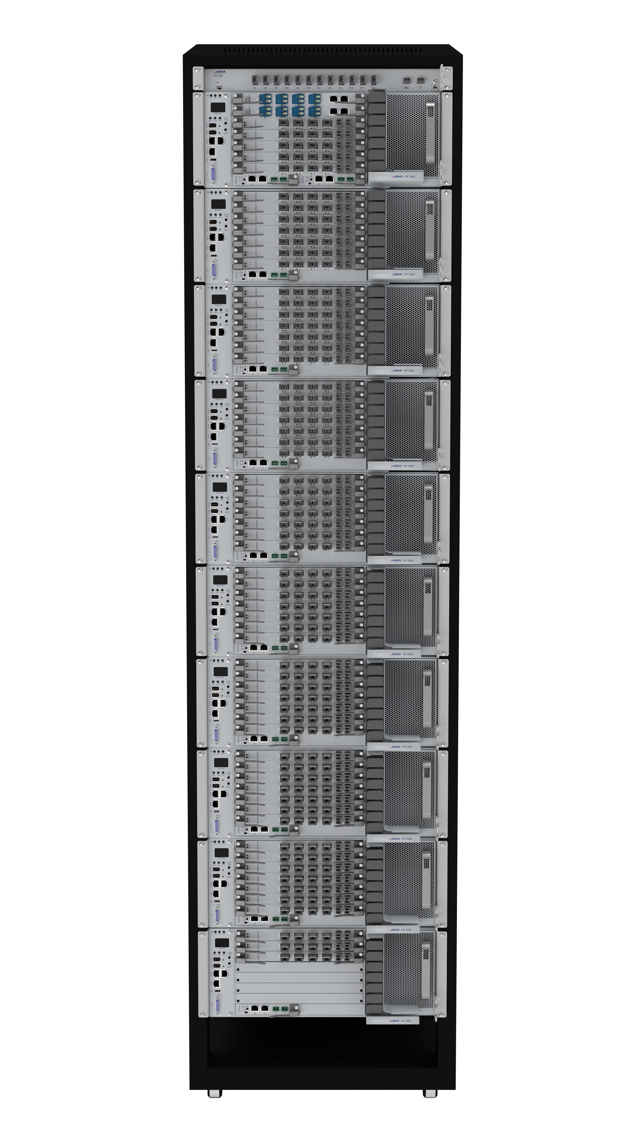 ADVA CloudConnect configuration supporting 25.6 Tbps line side capacity. Source: ADVA Optical Networking
The last CloudConnect chassis configuration is for customers designing a global cluster. Here the chassis has 10 SH4R units housing 64 QuadFlex cards to achieve a total transport capacity of 25.6 Tbps and a throughput of 51.2 Tbps.
Also included are 2 EDFAs and a 128-channel multiplexer. Two EDFAs are needed because of the optical loss associated with the high number of channels, such that an EDFA is allocated for each of the 64 channels. “For the [14 RU] 40 channels [configuration], you need only one EDFA,” says Theodoras.
The vendor has also produced a similar-sized configuration for the L-band. Combining the two 40 RU chassis delivers 51.2Tbps of transport and 102.4 Tbps of throughput. “This configuration was built specifically for a customer that needed that kind of throughput,” says Theodoras.
Other platform features include bulk encryption. ADVA says the encryption does not impact the overall data throughput while adding only a very slight latency hit. “We encrypt the entire payload; just a few framing bytes are hidden in the existing overhead,” says Theodoras.
The security management is separate from the network management. “The security guys have complete control of the security of the data being managed; only they can encrypt and decrypt content,” says Theodoras.
CloudConnect consumes only 0.5W/ Gigabit. The platform does not use electrical multiplexing of data streams over the backplane. The issue with using such a switched backplane is that power is consumed independent of traffic. The CloudConnect designers has avoided this approach. “The reason we save power is that we don’t have all that switching going on over the backplane.” Instead all the connectivity comes from the front panel of the cards.
The downside of this approach is that the platform does not support any-port to any-port connectivity. “But for this customer set, it turns out that they don’t need or care about that.”
Open hardware and software
ADVA Optical Networking claims is 4 RU basic unit addresses a sweet spot in the marketplace. The CloudConnect also has fewer inventory items for the data centre operators to manage compared to competing designs based on 1 RU or 2 RU pizza boxes, it says.
Theodoras also highlights the system’s open hardware and software design.
“We will let anybody’s hardware or software control our network,” says Theodoras. “You don’t have to talk to our software-defined networking (SDN) controller to control our network.” ADVA was part of a demonstration last year whereby an NEC and a Fujitsu controller oversaw ADVA’s networking elements.
Every vendor is always under pressure to have the best thing because you are only designed in for 18 months
By open hardware, what is meant is that programmers can control the optical line system used to interconnect the data centres. “We have found a way of simplifying it so it can be programmed,” says Theodoras. “We have made it more digital so that they don’t have to do dispersion maps, polarisation mode dispersion maps or worry about [optical] link budgets.” The result is that data centre operators can now access all the line elements.
“At OFC 2015, Microsoft publicly said they will only buy an open optical line system,” says Theodoras. Meanwhile, Google is writing a specification for open optical line systems dubbed OpenConfig. “We will be compliant with Microsoft and Google in making every node completely open.”
General availability of the CloudConnect platforms is expected at the year-end. “The data centre interconnect platforms are now with key partners, companies that we have designed this with,” says Theodoras.
Clusters, pods and recipes explained
A cluster is made up of a number of virtual machines and CPU cores and is defined in software. A cluster is a virtual entity, says Theodoras, unrelated to the way data centre managers define their hardware architectures.
“Clusters vary a lot [between players],” says Theodoras. “That is why we have had to make scalability such a big part of CloudConnect.”
The hardware definition is known as a pod or recipe. “How these guys build the network is that they create recipes,” says Theodoras. “A pod with this number of servers, this number of top-of-rack switches, this amount of end-of-row router-switches and this transport node; that will be one recipe.”
Data centre players update their recipes every 18 months. “Every vendor is always under pressure to have the best thing because you are only designed in for 18 months,” says Theodoras.
Vendors are informed well in advance what the next hardware requirements will be, and by when they will be needed to meet the new recipe requirements.
In summary, pods and recipes refer to how the data centre architecture is built, whereas a cluster is defined at a higher, more abstract layer.
Moore's law and silicon photonics
Chip pioneer Gordon E. Moore’s article appeared in the magazine Electronics in 1965. Dr. Moore was the director of the R&D labs at Fairchild Semiconductor, an early maker of transistors. Moore went on to co-found Intel, then a memory company, becoming its second CEO after Robert Noyce.
Moore’s article was written in the early days of integrated circuits. At the time, silicon wafers were one inch in diameter and integrating 50 components on a chip was deemed a state-of-the-art design.
Moore observed that, at any given time, there was an ideal number of components that achieved a minimum cost. Add a few more components and the balance would be tipped: the design would become overly complex, wafer yields would go down and costs would rise.
His key insight, later to become known as Moore’s law, was that integrated circuit complexity at this minimum cost was growing over time. Moore expected the complexity to double each year for at least another decade.
In his article he predicted that, by 1970, the manufacturing cost per component would be a tenth of the cost in 1965. Extrapolating the trend further, Moore believed that “by 1975, the number of components per integrated circuit for minimum cost will be 65,000 components.” Moore was overly optimistic, but only just: in 1975, Intel was developing a chip with 32,000 transistors.
“Perhaps we can say that the future of silicon photonics is the future of electronics itself.”
One decade after his article, Moore amended his law to a doubling of complexity every 24 months. By then the industry had started talking about transistors rather than components - circuit elements such as transistors, resistors and capacitors - after alighting on complementary metal oxide semiconductor (CMOS) technology to make the bulk of its chips. And in the years that followed, the period of complexity-doubling settled at every 18 months.
Moore has received less credit for his article's remarkable foresight regarding the importance of integrated circuits, especially when, in 1965, their merits were far from obvious. Such devices would bring a proliferation of electronics, he said, “pushing this science into many new areas”.
He foresaw home computers “or at least terminals connected to a central computer’, automatic control for automobiles and even mobile phones - ‘personal portable communications equipment’ as he called them. The biggest potential of ICs, he said, would be in the making of systems, with Moore highlighting computing, and telephone communications and switches.
The shrinking transistor
The shrinking of the transistor has continued ever since. And the technological and economic consequences have been extraordinary.
As a recent 50th anniversary Moore’s law article in IEEE Spectrum explains (link above), the cost of making a transistor in 1965 was $30 at today’s costs, in 2015 it is one billionth of a dollar. And in 2014, the semiconductor industry made 250 billion billion transistors, more transistors than had been made in all the years of the semiconductor industry up to 2011.
But the shrinking of the transistor cannot continue indefinitely, especially as certain transistor dimensions approach the atomic scale. As a result, many of the benefits that resulted with each shift to a new, smaller feature-sized CMOS process no longer hold.
To understand why, some understanding of CMOS and in particular, the MOS field effect transistor (MOSFET), is required.
Current flow between a MOSFET’s two terminals - the source and the drain - is controlled by a voltage placed on a third, electrical contact known as a gate. The gate comprises a thin layer of metal oxide, an oxide insulator on which sits a metal contact.
Several key dimensions define the MOSFET including the thickness of the oxide, the width of the source and the drain, and the gate length - the distance between the source and the drain.
Dennard scaling, named after IBM engineer and inventor of the DRAM, Robert Dennard, explains how the key dimensions of the transistor can all shrunk by the same factor, generation after generation. It is the effect of this scaling that makes Moore’s law work.
From the 1970s to the early 2000s, shrinking the transistor’s key dimension by a fixed factor returned a guaranteed bounty. More transistors could be placed on a chip allowing more on-chip integration, while each transistor became cheaper.
In turn, for a given chip area, the chip’s power density - the power consumption over a given area - remained constant. There may be more transistors crammed into a fixed area but the power each one consumes is less.
The predictable era of scaling transistors, after 50 years, is coming to an end and the industry is set to change
The transistor gate length feature size is used to define the CMOS technology or process node. In 1980, the minimum feature size was around 3 microns, nowadays CMOS chips typically use a 28 nanometer feature size - a 100 fold reduction. The metal oxide thickness has also been reduced one hundred times over the years.
But in the last decade Dennard scaling has come to an end.
The gate’s oxide thickness can no longer be trimmed as its dimensions are only a few atoms thick. The voltage threshold, the voltage applied to the gate to turn the transistor on, has also stopped shrinking, which in turn has stopped the scaling of the transistor’s upper voltage.
Why is this important? Because no longer being able to scale all these key parameters has meant that while smaller transistors can still be made, their switching speed is no longer increasing, nor is the power density constant.
Moreover, the very success of the relentless scaling means that the transistors are so tiny that new effects have come into play.
Transistors now leak current even when they are in the ‘off’ state. This means they consume power not only when they are being switched at high speed - the active power - but also they consume leakage power when they are off due to this current.
Process engineers now must work harder, to develop novel transistor designs and new materials to limit the leakage current. A second issue associated with the prolonged success of Dennard scaling is variability. Transistors are now less reliable and their performance less predictable.
The end of Dennard scaling means that the chip companies’ motivation to keep shrinking transistors is more to do with device cost rather than performance.
If, before, the power density stayed fixed with each new generation of CMOS process, more recently it has been the cost of manufacturing of a given area of silicon that has stayed fixed.
As the IEEE Spectrum Moore’s law article explains, this has been achieved by a lot of engineering ingenuity and investment. Device yield has gone up from 20 percent in the 1970s to between 80 and 90 percent today. The size of the silicon wafers on which the chips are made has also increased, from 8 inches to 12 inches. And while the lithography tools now cost one hundred-fold more than 35 years ago, they also pattern the large wafers one hundred times faster.
But now even the cost of making a transistor has stopped declining, according to The Linley Group, with the transition point being around the 28nm and 20nm CMOS.
Silicon manufacturing innovation will continue, and transistors will continue to shrink. Leading chip companies have 14nm CMOS while research work is now at a 7nm CMOS process. But not everyone will make use of the very latest processes, given how these transistors will be more costly.
Beyond Moore’s law
The industry continues to debate how many years Moore’s law still has. But whether Moore’s law has another 10 years or not, it largely does not matter.
Moore’s law has done its job and has brought the industry to a point where it can use billions of transistors for its chip designs.
But to keep expanding computing performance, new thinking will be required at many levels, spanning materials, components, circuit design, architectures and systems design.
The predictable era of scaling transistors, after 50 years, is coming to an end and the industry is set to change.
IBM announced last year its plan to invest US $3 billion over five years to extend chip development. Areas it is exploring include quantum computing, neurosynaptic computing, III-V technologies, carbon nanotubes, graphene, next-generation low-power transistors, and silicon photonics.
Silicon photonics
The mention of silicon photonics returns us to Gordon Moore’s 1965 article. The article starts with a bang: “The future of integrated electronics is the future of electronics itself".
Can the same be said of photonics?
Is the future of integrated photonics the future of photonics itself?
Daryl Inniss, vice president of Ovum’s components practice, argues this is certainly true. Photonics may not have one optical building block like electronics has the transistor, nor is there any equivalent of Dennard scaling whereby shrinking photonic functions delivers continual performance benefits.
But photonic integration does bring cost benefits, and developments in optical interconnect and long-haul transmission are requiring increasing degrees of integration, the sort of level of component integration associated with the chip industry at the time of Moore’s article.
And does the following statement hold true? “The future of silicon photonics is the future of photonics itself.”
“I think silicon photonics is bigger than photonics itself,” says Inniss. “Where do you draw the line between photonics and electronics? IBM, Intel and STMicroelectronics are all suppliers of electronics.”
Inniss argues that silicon photonics is an electronics technology. “Perhaps we can say that the future of silicon photonics is the future of electronics itself.”