How DSP smarts continue to improve optical transport
- Kim Roberts explains the signal processing techniques Ciena is using for its WaveLogic 6 coherent DSP.
- Roberts explains how the techniques squeeze, on average, a 15 per cent improvement in spectral efficiency.
- The WaveLogic 6 Extreme chip can execute 1,600 trillion (1.6 x 10¹⁵) operations per second and uses the equivalent of 4km of on-chip copper interconnect.
Part 2: WaveLogic 6’s digital signal processing toolkit
Bumping into Kim Roberts on the way to the conference centre at OFC, held in San Diego in March, I told him how, on the Ciena briefing about its latest WaveLogic 6 coherent digital signal processor (DSP), there had been insufficient time to dive deeply into the signal processing techniques used.
“What are you doing now?” said Roberts.
“I’m off to the plenary session to catch the keynotes.”
Chatting some more, I realised I was turning down a golden opportunity to sit down with a leading DSP and coherent modem architect.
“Is that offer still open?” I asked.
He nodded.
We grabbed a table at a nearby cafe and started what would prove to be an hour-long conversation.
High-end coherent DSPs
Many leading coherent modem vendors unveiled their latest designs in the run-up to the OFC show. It is rare for so many announcements to be aligned, providing a valuable glimpse of the state of high-performance optical transport.
Nokia announced its PSE-6s, which has a symbol rate of up to 130 gigabaud (GBd) and supports 1.2 terabit wavelengths. Infinera announced its 1.2-terabit ICE-7, which has a baud rate of up to 148GBd, while Fujitsu detailed it is using its 135GBd 1.2-terabit wavelength coherent DSP for its 1FINITY Ultra optical platform.
Meanwhile, Acacia, a Cisco company, revealed its 140GBd Jannu 1.2-terabit DSP has been shipping since late 2022. Acacia announced the Jannu DSP in March 2022.
All these coherent DSPs are implemented using 5nm CMOS and are shipping or about to.
And Ciena became the first company to detail a coherent DSP fabricated using a 3nm CMOS process. The WaveLogic 6 Extreme supports 1.6-terabit wavelengths and has a symbol rate of up to 200GBd.
Ciena’s WaveLogic 6 Extreme improves spectral efficiency by, on average, 15 per cent. WaveLogic 6 Extreme-based coherent modems will be available from the first half of 2024.
Customer considerations
Kim Roberts begins by discussing what customers want.
“With terrestrial systems, it is cost-per-bit [that matters], and if you’re not going very far, it is cost-per-modem,” says Roberts.
For the shortest reaches (tens of km), 100 gigabit may be enough while 200 gigabit or more is overkill. Here, a coherent pluggable module does the job.
“What matters is the cost per modem to get the flexibility of coherent connectivity so that you can plug it in and it works,” says Roberts.
With medium and long-haul terrestrial routes, cost-per-bit and heat-per-bit are the vital issues. With heat, area and volume of the coherent design are important. “I need volume to get the heat out of the chip on the card and into the air,” says Roberts.
Another use case is where spectral efficiency is key, for networks where fibre is scarce. An operator could be leasing dark fibre, or it could be a submarine network.
Ciena’s WaveLogic 6 Extreme’s 15 per cent improvement in spectral efficiency improves capacity over the same link. “Equivalently, you can go a dB (decibel) further or have a dB more signal margin,” says Roberts.
A common refrain heard is that spectral efficiency is no longer improving due to the Shannon limit being approached. Shannon’s limit is being approached because of the considerable progress already made by the industry in coherent optics.
“There is no 6dB to be had like in the old days,” says Roberts. “WaveLogic 3 was 2.5dB better than WaveLogic 2, but those multiple dBs are no longer there.”
The returns are diminishing, but striving for improvements remains worthwhile. “If you’re an operator that cares about spectral efficiency, that’s important,” he says.
Nonlinearity mitigation
Roberts returns to the issue of Shannon’s limit, based on the work of famed mathematician and information theorist, Claude Shannon.
“Shannon defines a theoretical limit for the capacity of a channel having linear propagation with additive Gaussian noise,” says Roberts.
This defines a strict mathematical limit, and it is pointless to go beyond that; he says: “In terms of linear performance, modems are getting close to the limit, within a couple of dB.”
Shannon’s limit doesn’t wholly define fibre since the channel is nonlinear.
Roberts says there is a whole research area addressing the bounds given such nonlinearities.
“We’re a long way from those theoretical nonlinear limits, but what matters is what’s the practical limit, and it’s getting hard,” he says
Increasing transmit power improves the optical signal-to-noise ratio (OSNR) and strengthens nonlinearities. Indeed, the nonlinearities grow faster with increased transmit power until, eventually, they dominate.
Because tackling nonlinearities is so complicated, Ciena’s approach is to approximate the problem as a linear Gaussian noise channel and do everything possible to mitigate the effects of nonlinearity rather than embrace it.
This is done by compensating at the transmitter the nonlinearities expected to happen along the fibre. The receiver performs measurements on a second-by-second basis and sends the results back. These are used as estimates of the anticipated nonlinearity about to be encountered and subtracted from the symbols to be sent.
Even though the exact nonlinearity is unknown, this is still a valid approximation. “It gives a quarter to one dB of performance improvement,” says Roberts
Edgeless clock recovery
Robert explains other clever signal processing techniques that buy a 6 per cent spectral efficiency improvement.
With wavelength division multiplexing (WDM), the laser-generated signals are placed next to each other across the fibre’s spectrum.
For WaveLogic 6, when running at its maximum symbol rate of 200 gigabaud, the spectrum occupies a 200GHz-wide channel.
Usually, the signal in the frequency domain is not perfectly square-shaped; the signal rolls off in the frequency domain so that in the time domain there is no inter-symbol interference. “But [as a result] you’re wasting spectrum; you are not fully using that spectrum,” says Roberts.
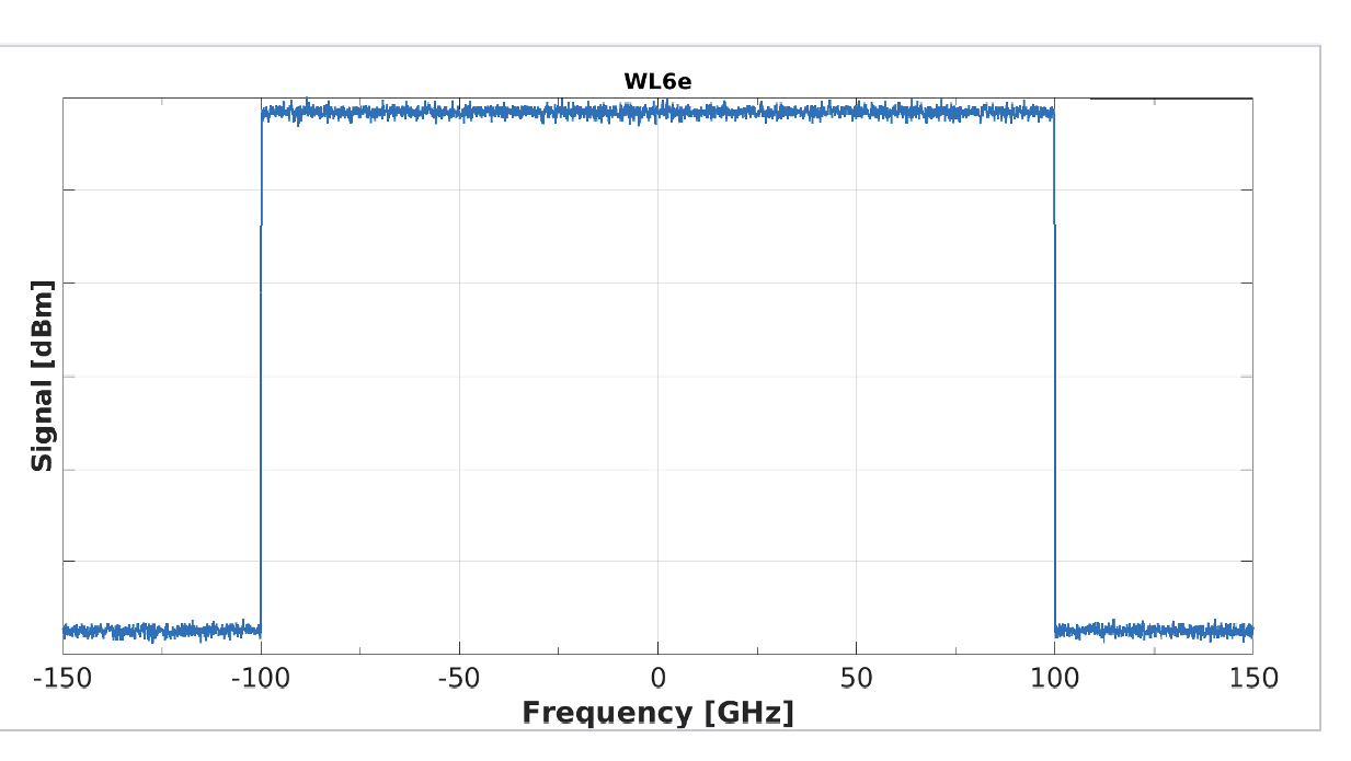
With WaveLogic 6, Ciena has created an idealised flat-topped, vertically edged signal spectra allowing the signals to be crammed side by side thereby making best use of the fibre’s spectrum (see diagram).
The challenge is that the clocking information used for data recovery at the receiver resided in this roll-off region. Now, that is no longer there so Cienahas developed another method to recover clock information.
A second challenge with signal recovery is that the transmit laser and the receive laser are not rigidly fixed in frequency. Being so close together, care is needed to recover only the wavelength – signal – of interest.
Yet another complication is how a rectangle in the frequency domain causes the signal in the time domain to ‘ring’ and go on forever.
“There are several signal processing methods that we had to develop to make this possible,” says Roberts.
Frequency-division multiplexing
Ciena also uses frequency division multiplexing (FDM), a technique it first introduced with the WaveLogic 5 Extreme.
The difference between WDM and FDM, explains Roberts, is that WDM uses different lasers to generate the wavelengths while FDM is generated by applying digital techniques to the same laser. “You are digitally combining different streams,” he says.
This is useful because it turns out that each fibre route has an optimum baud rate because of nonlinearities.
“If I’m using the full symbol rate of 200GBd, I can divide that into parallel streams, which behave as if they were independent circuits as far as nonlinearity is concerned,” says Roberts. “The optimum number of FDM in your spectrum is proportional to the square root of the total amount of dispersion, so high dispersion, more FDMs, low dispersion, just one.”
Ciena first added the option of four FDM with the WaveLogic 5. Now, WaveLogic 6 implements 1,2,4, and 8 FDM channels.

“For short distances, you want to go one signal at 200 gigabaud, or smaller if you’re reducing baud rate, but if you’re going very long distances, lots of dispersion, you go at eight parallel streams being sent at 25 gigabaud each,” he says.
But introducing FDM causes notches in the near-idealised rectangular spectrum mentioned earlier. Ciena has had to tackle that too.
“If you measure the spectrum, it’s completely flat, there are no notches between the FDMs, there is no wasted spectrum,” says Roberts.
Multi-dimensional coding
Multi-dimensional coding is a further technique used by Ciena to improve optical transmission, especially in troublesome cables where there are much nonlinearity and noise. It is challenging to get information through.
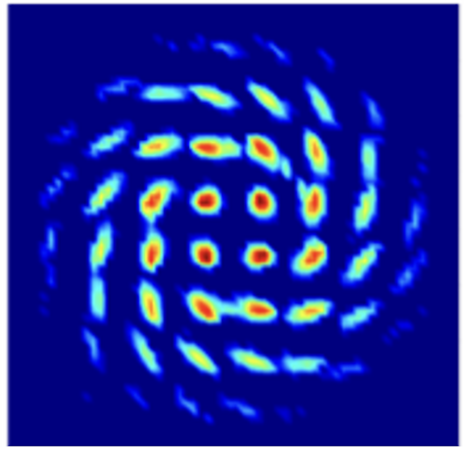
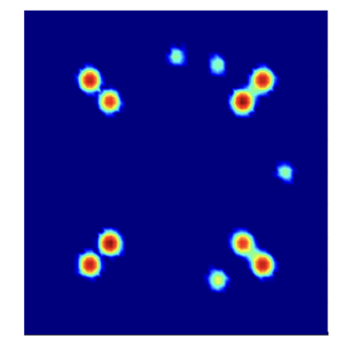
To understand multi-dimensional constellations, Roberts uses the example of a 16-QAM constellation, which he describes as a two-dimensional (2D) representation in one polarisation.
But if both polarisations of light are considered one signal, it becomes a 4D, 256-point (16×16) symbol. This can be further extended by including the symbols in adjacent time slots to form an 8D representation.
Ciena introduced this technique with its WaveLogic 3 Extreme coherent DSP, which supported the multi-dimension coding scheme 8D-2QAM to improve the reach or capacity of long-reach spans.
Now Ciena has introduced a family of such multi-dimensional schemes with WaveLogic 6 Extreme, executing in regions of very high nonlinearity and noise. These include 4, 8, and 16-dimensional constellations.
An example where the technique is used includes cases where there is twice as much noise as there is signal. “So the signal-to-noise ratio is -3dB,” says Roberts. Yet even here, 100 gigabits can still get through.
WaveLogic 6 Nano
Ciena also announced its 3nm CMOS WaveLogic 6 Nano DSP aimed at pluggable coherent modules. Is the Nano’s role to implement a subset of the signal processing capabilities of the Extreme?
Here, the customer’s requirements are different: heat, space and footprint are the dominant concerns. The Nano has to fit the heat envelope of the different sizes of pluggables, says Roberts. The optical performance is chosen based on fitting that heat requirement.
One of the merits of 3nm FinFET transistor technology is that if you don’t clock a circuit, only 1 per cent of the heat is generated compared to when it’s clocked, notes Roberts: “So, for different features, I can turn off the clock.”
A suitcase still full of tools?
At the time of the WaveLogic 5 launch, Roberts mentioned that there were still many tools left in the suitcase of ideas. Is this still true with the WaveLogic 6?
For Roberts, the question is: will it be economically viable to put in new capabilities based on the heat and performance and in terms of the size, schedule, and the amount of work involved?
Then, with a broad smile, he says: “There is room to occupy us as to how to get the next 10 to 20 per cent of spectral efficiency.”
And with that, we each set off for a day of meetings.
Roberts headed off to his hotel before his 10am meeting. I set off for the OFC exhibition hall and a meeting with the OIF.
As I walked to the convention centre, I kept thinking about the impromptu briefing and how I so nearly passed up on Roberts’ expertise and generosity.

WaveLogic 5: Packing a suitcase of ideas in 7nm CMOS
-
Ciena’s WaveLogic 5 coherent digital signal processor family comprises the Extreme and Nano chips
-
The WaveLogic 5 Extreme maximises optical capacity and transmission reach while the WaveLogic 5 Nano is targeted at compact, power-conservative applications
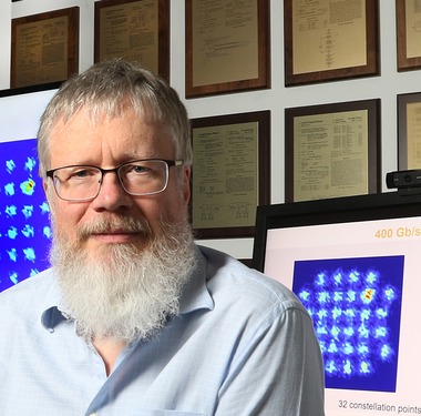
Kim Roberts
Advancing coherent optical transmission performance; targeting the emerging coherent pluggable market; selling modules directly, and the importance of being more vertically integrated. All these aspects were outlined by Cisco to explain why it intends to buy the coherent optical transmission specialist, Acacia Communications; a deal that is set to be completed in the spring of 2020.
But such strategic thinking is being pursued by Ciena with its next-generation WaveLogic 5 family of coherent DSPs.
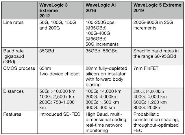
The WaveLogic 5 continues Ciena’s tradition of issuing a coherent digital signal processor (DSP) family approximately every three years: Ciena announced the WaveLogic 3 in 2012 and the WaveLogic Ai in 2016. (Add links).
The company has managed to maintain its three-yearly cadence despite the increasing sophistication of each generation of coherent DSP. For example, the WaveLogic 5 Extreme will support 800 gigabits-per-wavelength, double Ciena’s WaveLogic Ai that has been shipping for nearly two years.
Kim Roberts, vice president of WaveLogic science, says Ciena has managed to deliver its coherent DSPs in a timely manner since much of the algorithmic development work was done 5-6 years ago. The issue has been that certain features developed back then could not be included within the WaveLogic Ai.
WaveLogic 5 is implemented using a 7nm FinFET CMOS process whereas the WaveLogic Ai uses a 28nm specialist CMOS process known as fully-depleted silicon-on-insulator (FD-SOI).
“Seven-nanometer CMOS, due to its density and low heat, allows us to implement things that didn’t make the cut for the WaveLogic Ai,” says Roberts.
The company has a ‘suitcase of ideas’, he says, but not all of the concepts make it into any one generation of chip. “They have to justify performance versus schedule versus heat [generated],” says Roberts. “As we improve the technology, more features make the cut.”
And there are developments that will be included in future designs: “We keep refilling the suitcase,” says Roberts.
NAMING
Ciena first used the Extreme and Nano nomenclature with the WaveLogic 3. In contrast, the WaveLogic Ai, when launched in 2016, was a single-chip targeting the high-end. Ciena chose to change the naming scheme with the Ai since the chip signified a shift with features such as network monitoring.
However, Ciena highlights a key difference between the WaveLogic 3 and WaveLogic 5 families. The WaveLogic 3 Extreme and the WaveLogic 3 Nano could talk to each other on appropriate spans. In contrast, the two WaveLogic 5 chips are distinct. “They are not designed to interwork,” says Roberts.
NETWORKING TRENDS
Telecom service providers are investing in their networks to make them more adaptive. They want their networks to be scalable and programmable, says Ciena.
The operators also want to better understand what is happening in their networks and that requires collecting data, performing analytics and using software to configure their networks in an automated way.
“How do you get there? It is all about coherent technology,” says Helen Xenos, senior director, portfolio marketing at Ciena. “It is a critical element that is helping operators scale their networks.”
By enhancing the traffic-carrying capacity of fibre, coherent technology enables operators to reduce transport costs. “It allows them to be more competitive as they can do more with the hardware they deploy,” says Xenos.

Helen Xenos
Both telcos and cable operators are also applying coherent technology to new applications in their networks such as access.
These transport needs are causing a divergence in requirements.
One is to keep advancing optical performance in terms of the spectral efficiency and the traffic-carrying capacity of links. This is what the WaveLogic 5 Extreme tackles.
The second requirement - producing a compact coherent design for the network edge - is addressed by the WaveLogic 5 Nano.
For access designs, what is important is a compact design where the optics and the DSP can operate over an extended temperature range.
The Nano also addresses the hyperscalers’ need to connect their distributed data centres across a metro. “They need high capacity - 400 gigabits - and short-reach connectivity,” says Xenos. “It really needs to be the smallest footprint to maximise density.”
VERTICAL INTEGRATION
In addition to unveiling the WaveLogic 5 Extreme and Nano ICs, Ciena has outlined how it is more vertically integrated after investing in optics. In 2016, Ciena acquired the high-speed photonics division of Teraxion, gaining expertise in indium phosphide and silicon photonics expertise. {add link}.
Ciena is also now selling coherent optical modules. Gazettabyte revealed last year that Ciena was planning to sell modules using its own optics and WaveLogic technologies. {add link}
The company has no preference regarding indium phosphide and silicon photonics and uses what is best for a particular design.
“Silicon photonics buys you ease-of-manufacturing and cost; indium phosphide is what you need for 800 gigabits,” says Xenos.
Ciena stresses, however, that there is no simple formula as to when each is preferred. In terms of size and heat, silicon photonics has a strong advantage. “In terms of performance, you get better performance in some instances with indium phosphide and then there are overlaps because you bring in cost and other constraints,” says Roberts. “So there is no simple divide.”
“As we move forward, we are going to see an increasing percent of Ciena-custom components in WaveLogic coherent modems,” says Xenos.
Source: Gazettabyte
EXTREME
The WaveLogic 5 Extreme introduces several developments. It operates at specific baud rates ranging from 60 to 95 gigabaud. The baud rates are chosen so that both fixed-grid 100GHz channels and flexible grid ones are supported.
“For the best performance, you have flexible grid when 95 gigabaud is the primary baud rate,” says Roberts.
It is also Ciena’s first coherent DSP that uses probabilistic constellation shaping, a coding scheme used to achieve granular capacity increments. {add link}
“From 200 gigabits to 800 gigabits [in 25-gigabit increments], optimised over any path or the available margin,” says Roberts. “But what is unique about this is that it is optimised for non-linear propagation.”
Initially, the products using the WaveLogic 5 Extreme will use 50-gigabit increments. “This is what is required to service customers’ client requirements today: ten gigabits and multiples of 100-gigabit clients,” says Xenos.
>
“With 25-gigabit steps in client rate, the customer can choose to spend the margin on sending more bits”
The DSP uses four-wave frequency-division multiplexing to mitigate non-linear impairments, particularly beneficial for sub-sea systems.
Ciena says the four-wave frequency-division multiplexing is achieved electrically, reducing the optics to a minimum. “One laser and one modulator are used, so all the [cost-saving] economics of a single optical wavelength,” says Roberts. “But it has the non-linear performance of four tightly-coupled electrical systems.”
Ciena has also added an improved forward-error correction (FEC) scheme - a ‘throughput-optimised FEC’ - that uses variable overhead bits depending on the client rate.
“It will handle 8.6 percent errors compared to what we used in the WaveLogic Ai which handles 3.5 percent errors,” says Roberts. “So it is a decibel better.”
The Extreme chip also has improved link-monitoring capabilities. It monitors the signal-to-noise per channel as well as quantifies the non-linear contributions. “It helps people to understand what is happening in the network and create algorithms to optimise the capacity across the network,” says Xenos.
PROBABILISTIC CONSTELLATION SHAPING
Probabilistic shaping is used to improve the optical performance by lowering the signal energy by not using all the constellation points. Unless, that is, the full data rate is used and then all the constellation points are needed.
The degree of probabilistic shaping used is determined for each link. The parameters used to determine the probabilistic shaping are the amount of dispersion on the link, the span’s reach, and the transmitted client rate.
“The modem will measure what is going on in the link and the customer or some higher-level software will say what the client rate is,” says Roberts. “The modem will then figure out how to do the best non-linear probabilistic shaping to support that rate on the link.”
Roberts says other firms’ probabilistic shaping use one symbol at a time whereas Ciena use blocks, each comprising 128 symbols. “A bigger number would be better but I'm limited by my hardware,” says Roberts.
The 128 symbols equate to 1024 bits: four magnitude bits using 64-ary quadrature amplitude modulation (64-QAM) multiplied by two, one for each polarisation.
This means there are a total of 2^1024 combinations of 1024-bit sequences that could be sent. However, when sending a 400 Gigabit Ethernet (GbE) client signaland, for the benefit of explanation, assuming that 555 bits are needed to carry the data payload and the overhead, the number of possible bit sequences is trimmed to 2^555.
This is still a fantastically huge number but the DSP can work out which are the best 555-bit sequences to send based on them having the most tolerance to linear and non-linear interference.
“The ones that play nicely with their neighbours such that they cause the minimum non-linear degradation on the neighbouring wavelengths and on the other symbols,” explains Roberts.
Ciena is not forthcoming as to how it calculates the best sequences. “Ciena’s algorithms decide which ones are best,” says Xenos. “This is one of our key differentiators.”
The result is that, depending on the fibre type, a 1.5dB performance improvement is achieved for the non-linear characteristics.
“It allows more capacity to be chosen by the customer on that same link,” says Roberts. “With 25-gigabit steps in client rate, the customer can choose to spend the margin on sending more bits.”
Operating the Extreme at 95GBd, a reach of 4,000 km is possible at 400 gigabits and at 600 gigabits, the reach is 1,000 km (see table).
WAVELOGIC 5 NANO
The WaveLogic Nano supports 100-gigabit to 400-gigabit wavelengths and is aimed at applications that need compact designs that generate the least heat.
One application is to enable cable operators to move optics closer to the user and that must operate over an extended temperature range. Here, a packet platform is used that will support line interworking as equipment from different vendors may be at each end of the link.
Another requirement is operating over multiple spans in a metro. Here, compact equipment and low power are more important than spectral efficiency but it is still a challenging environment, says Ciena. Hundreds of nodes may be talking to each other and there may be cascaded reconfigurable optical add-drop multiplexers (ROADMs) with different fibre types making up the network.
A third application is single-span data centre interconnect where achieving the highest density on routers is key. This is the application the 400-gigabit, at least 80km 400ZR specification developed by the Open Internetworking Forum will address.
“The design that we are doing for the WaveLogic 5 Nano for 400ZR is to fit into a QSFP-DD,” says Xenos. “If there is a need for an OSFP [pluggable module], we will offer OSFP.”
Ciena also expects to offer a Nano-based CFP2-DCO module, which will outperform the ZR in terms of reach and features, for more demanding metro applications.
Another new segment requiring coherent optics is 4G and 5G access. “It is to be determined what type of platform is the winning solution in this environment,” says Xenos.
MAKING MODULES
Ciena first made its coherent DSP available to third parties in 2017 when it signed an agreement with Lumentum, NeoPhotonics and at the time Oclaro (since acquired by Lumentum) to use its WaveLogic Ai in their modules.
Now Ciena is selling directly the full coherent modem: the DSP and the optics. This is why Ciena created its Optical Microsystems unit in late 2017.
CMOS PROCESS
Moving to a 7nm FinFET CMOS process delivers several benefits.
It generates much lower heat than the WaveLogic Ai’s 28nm FD-SOI process. It also has a lower quiescent current, the current dissipated independent of whether the chip’s logic is active or not. And 7nm CMOS delivers much greater circuit density: the functionality that can be crammed into a square micrometre of silicon.
“So, a low power [consumption] on features you are not using, and we can include features that if you can't afford the heat, you can turn them off,” says Roberts.
It will offer its Nano in the form of pluggable modules, the WaveLogic Ai as a 5x7-inch module, and the WaveLogic 5 Extreme in another module form factor that will have its own interface. “These would all be viable optics,” says Xenos.
Availability
The first Wave Logic 5 Nano products will appear in the second half of this year while the first Extreme-based products will be available at the end of this year. The 400ZR coherent pluggable module is expected to be available in the first half of 2020.

Heading off the capacity crunch
Improving optical transmission capacity to keep pace with the growth in IP traffic is getting trickier.
Engineers are being taxed in the design decisions they must make to support a growing list of speeds and data modulation schemes. There is also a fissure emerging in the equipment and components needed to address the diverging needs of long-haul and metro networks. As a result, far greater flexibility is needed, with designers looking to elastic or flexible optical networking where data rates and reach can be adapted as required.
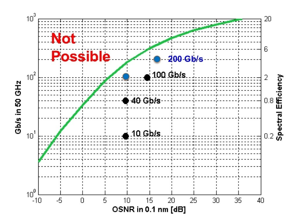
 Figure 1: The green line is the non-linear Shannon limit, above which transmission is not possible. The chart shows how more bits can be sent in a 50 GHz channel as the optical signal to noise ratio (OSNR) is increased. The blue dots closest to the green line represent the performance of the WaveLogic 3, Ciena's latest DSP-ASIC family. Source: Ciena.
But perhaps the biggest challenge is only just looming. Because optical networking engineers have been so successful in squeezing information down a fibre, their scope to send additional data in future is diminishing. Simply put, it is becoming harder to put more information on the fibre as the Shannon limit, as defined by information theory, is approached.
"Our [lab] experiments are within a factor of two of the non-linear Shannon limit, while our products are within a factor of three to six of the Shannon limit," says Peter Winzer, head of the optical transmission systems and networks research department at Bell Laboratories, Alcatel-Lucent. The non-linear Shannon limit dictates how much information can be sent across a wavelength-division multiplexing (WDM) channel as a function of the optical signal-to-noise ratio.
A factor of two may sound a lot, says Winzer, but it is not. "To exhaust that last factor of two, a lot of imperfections need to be compensated and the ASIC needs to become a lot more complex," he says. The ASIC is the digital signal processor (DSP), used for pulse shaping at the transmitter and coherent detection at the receiver.
Our [lab] experiments are within a factor of two of the non-linear Shannon limit, while our products are within a factor of three to six of the Shannon limit - Peter Winzer
At the recent OFC 2015 conference and exhibition, there was plenty of announcements pointing to industry progress. Several companies announced 100 Gigabit coherent optics in the pluggable, compact CFP2 form factor, while Acacia detailed a flexible-rate 5x7 inch MSA capable of 200, 300 and 400 Gigabit rates. And research results were reported on the topics of elastic optical networking and spatial division multiplexing, work designed to ensure that networking capacity continues to scale.
Trade-offs
There are several performance issues that engineers must consider when designing optical transmission systems. Clearly, for submarine systems, maximising reach and the traffic carried by a fibre are key. For metro, more data can be carried on a single carrier to improving overall capacity but at the expense of reach.
Such varied requirements are met using several design levers:
- Baud or symbol rate
- The modulation scheme which determines the number of bits carried by each symbol
- Multiple carriers, if needed, to carry the overall service as a super-channel
The baud rate used is dictated by the performance limits of the electronics. Today that is 32 Gbaud: 25 Gbaud for the data payload and up to 7 Gbaud for forward error correction and other overhead bits.
Doubling the symbol rate from 32 Gbaud used for 100 Gigabit coherent to 64 Gbaud is a significant challenge for the component makers. The speed hike requires a performance overhaul of the electronics and the optics: the analogue-to-digital and digital-to-analogue converters and the drivers through to the modulators and photo-detectors.
"Increasing the baud rate gives more interface speed for the transponder," says Winzer. But the overall fibre capacity stays the same, as the signal spectrum doubles with a doubling in symbol rate.
However, increasing the symbol rate brings cost and size benefits. "You get more bits through, and so you are sharing the cost of the electronics across more bits," says Kim Roberts, senior manager, optical signal processing at Ciena. It also implies a denser platform by doubling the speed per line card slot.
As you try to encode more bits in a constellation, so your noise tolerance goes down - Kim Roberts
Modulation schemes
The modulation used determines the number of bits encoded on each symbol. Optical networking equipment already use binary phase-shift keying (BPSK or 2-quadrature amplitude modulation, 2-QAM) for the most demanding, longest-reach submarine spans; the workhorse quadrature phase-shift keying (QPSK or 4-QAM) for 100 Gigabit-per-second (Gbps) transmission, and the 200 Gbps 16-QAM for distances up to 1,000 km.
Moving to a higher QAM scheme increases WDM capacity but at the expense of reach. That is because as more bits are encoded on a symbol, the separation between them is smaller. "As you try to encode more bits in a constellation, so your noise tolerance goes down," says Roberts.
One recent development among system vendors has been to add more modulation schemes to enrich the transmission options available.
From QPSK to 16-QAM, you get a factor of two increase in capacity but your reach decreases of the order of 80 percent - Steve Grubb
Besides BPSK, QPSK and 16-QAM, vendors are adding 8-QAM, an intermediate scheme between QPSK and 16-QAM. These include Acacia with its AC-400 MSA, Coriant, and Infinera. Infinera has tested 8-QAM as well as 3-QAM, a scheme between BPSK and QPSK, as part of submarine trials with Telstra.
"From QPSK to 16-QAM, you get a factor of two increase in capacity but your reach decreases of the order of 80 percent," says Steve Grubb, an Infinera Fellow. Using 8-QAM boosts capacity by half compared to QPSK, while delivering more signal margin than 16-QAM. Having the option to use the intermediate formats of 3-QAM and 8-QAM enriches the capacity tradeoff options available between two fixed end-points, says Grubb.
Ciena has added two chips to its WaveLogic 3 DSP-ASIC family of devices: the WaveLogic 3 Extreme and the WaveLogic 3 Nano for metro.
WaveLogic3 Extreme uses a proprietary modulation format that Ciena calls 8D-2QAM, a tweak on BPSK that uses longer duration signalling that enhances span distances by up to 20 percent. The 8D-2QAM is aimed at legacy dispersion-compensated fibre that carry 10 Gbps wavelengths and offers up to 40 percent additional upgrade capacity compared to BPSK.
Ciena has also added 4-amplitude-shift-keying (4-ASK) modulation alongside QPSK to its WaveLogic3 Nano chip. The 4-ASK scheme is also designed for use alongside 10 Gbps wavelengths that introduce phase noise, to which 4-ASK has greater tolerance than QPSK. Ciena's 4-ASK design also generates less heat and is less costly than BPSK.
According to Roberts, a designer’s goal is to use the fastest symbol rate possible, and then add the richest constellation as possible "to carry as many bits as you can, given the noise and distance you can go".
After that, the remaining issue is whether a carrier’s service can be fitted on one carrier or whether several carriers are needed, forming a super-channel. Packing a super-channel's carriers tightly benefits overall fibre spectrum usage and reduces the spectrum wasted for guard bands needed when a signal is optically switched.
Can symbol rate be doubled to 64 Gbaud? "It looks impossibly hard but people are going to solve that," says Roberts. It is also possible to use a hybrid approach where symbol rate and modulation schemes are used. The table shows how different baud rate/ modulation schemes can be used to achieve a 400 Gigabit single-carrier signal.

Note how using polarisation for coherent transmission doubles the overall data rate. Source: Gazettabyte
But industry views differ as to how much scope there is to improve overall capacity of a fibre and the optical performance.
Roberts stresses that his job is to develop commercial systems rather than conduct lab 'hero' experiments. Such systems need to be work in networks for 15 years and must be cost competitive. "It is not over yet," says Roberts.
He says we are still some way off from when all that remains are minor design tweaks only. "I don't have fun changing the colour of the paint or reducing the cost of the washers by 10 cents,” he says. “And I am having a lot of fun with the next-generation design [being developed by Ciena].”
"We are nearing the point of diminishing returns in terms of spectrum efficiency, and the same is true with DSP-ASIC development," says Winzer. Work will continue to develop higher speeds per wavelength, to increase capacity per fibre, and to achieve higher densities and lower costs. In parallel, work continues in software and networking architectures. For example, flexible multi-rate transponders used for elastic optical networking, and software-defined networking that will be able to adapt the optical layer.
After that, designers are looking at using more amplification bands, such as the L-band and S-band alongside the current C-band to increase fibre capacity. But it will be a challenge to match the optical performance of the C-band across all bands used.
"I would believe in a doubling or maybe a tripling of bandwidth but absolutely not more than that," says Winzer. "This is a stop-gap solution that allows me to get to the next level without running into desperation."
The designers' 'next level' is spatial division multiplexing. Here, signals are launched down multiple channels, such as multiple fibres, multi-mode fibre and multi-core fibre. "That is what people will have to do on a five-year to 10-year horizon," concludes Winzer.
For Part 2, click here
See also:
- Scaling Optical Fiber Networks: Challenges and Solutions by Peter Winzer
- High Capacity Transport - 100G and Beyond, Journal of Lightwave Technology, Vol 33, No. 3, February 2015.
A version of this article first appeared in an OFC 2015 show preview
2020 vision
In a panel discussion at the recent Level123 Terabit Optical and Data Networking conference, Kim Roberts, senior director coherent systems at Ciena, shared his thoughts about the future of optical transmission.
Final part : Optical transmission in 2020
 "Four hundred Gigabit and one Terabit are not going to start in long-haul"
Kim Roberts, Ciena
Kim Roberts starts on a cautionary note, warning of the dangers when predicting the future. "It is always wrong," he says. But in his role as a developer of systems, he must consider what technologies are going to be useful in 2020.
The simple answer is cheap, flexible optical spectrum and coherent modems (DSP-ASICs).
Since DSP-ASICs will become cheaper and consume less power as they are implemented using the latest CMOS processes, they will migrate from their initial use in long-haul/ regional networks to the metro and even the campus. "Four hundred Gigabit and one Terabit are not going to start in long-haul," says Roberts.
Traditionally, the long-haul network has been where new technology is introduced since it is the part of the network where premium prices can first be justified. "It is not going to start there; it won't have that reach," he says. Instead 400 Gigabit-per-second (Gbps) and one Terabit wavelengths will start over medium reaches - 500-700km - once they become more economical.
One consequence is that when going distances beyond medium reach, more spectrum will be required. "You'll have to light up more fibres [for long-haul], whereas in metro-regional you can put more down one fibre," says Roberts.
The current trend of greater functionality and intelligence being encapsulated in an ASIC will continue but Roberts does not rule out a new kind of optical device delivering a useful function. "It can happen quite suddenly - optical amplifiers happened really suddenly." That said, he does not see any such candidate optical technology for now.
The trends Roberts does expect through to 2020 are as follows:
- Optical pulse shaping: Technologies such as optical regeneration and optical demultiplexing have existed in the labs. But such techniques are not spectrally efficiency and are hot, large and expensive, he says. As a result, he does not expect them to become economical for commercial products by 2020.
- Photonic Switching: Optical burst switch, optical label switching, optical packet switching, all will not prove themselves to be economical by 2020. "Optics is not the right answer in the medium term," says Roberts.
- Optical wavelength conversion, optical logic, optical CDMA and optical solitons are other technologies in Roberts' view that will not be economical by 2020.
What Roberts does identify as being useful through 2020 are:
- Low loss, high dispersion, low non-linearities fibre: "New fibres from the likes of Sumitomo and Corning allow the exploitation of coherent modems," says Roberts. "High dispersion is good, it is your friend: it helps minimise non-linearities." This was not an accepted view as recently as 2005, he says, but now it is well accepted.
- Low cost, heat and noise, high-powered optical amplifiers: "This is a fairly simple function, let's just make them better and better," he says.
- Low cost, frequency-selective switching: This refers to taking a wavelength-selective switch (WSS) and getting rid of the ITU grid; making the WSS more flexible while lowering its cost and size.
- Coherent modems: As mentioned, these will improve in efficiency in terms of bits/s/dollar as well as higher performance in terms of decibels (dBs), reach and spectral efficiency. "Polishing these [metrics]," says Roberts.
Roberts admits that his useful items listed are not exciting, radical breakthroughs: "I think we are in an interval of improving on the trends we already have until there is some breakthrough."
Part 1: The capacity limits facing optical networking
Part 2: Optical transmission's era of rapid capacity growth
Further reading on photonic switching:
Packet optical transport: Hollowing the network core
Optical transmission's era of rapid capacity growth
Kim Roberts, senior director coherent systems at Ciena, moves from theory to practice with a discussion of practical optical transmission systems supporting 100Gbps, and in future, 400 Gigabit and 1 Terabit line rates. This discussion is based on a talk Roberts gave at the Layer123's Terabit Optical and Data Networking conference held in Cannes recently.
Part 2: Commercial systems
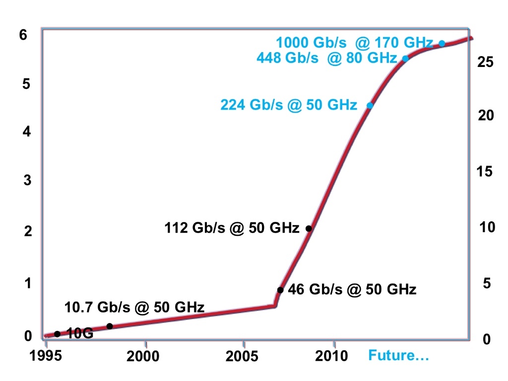
The industry is experiencing a period of rapid growth in optical transmission capacity. The years 1995 till 2006 were marked by a gradual increase in system capacity with the move to 10 Gigabit-per-second (Gbps) wavelengths. But the pace picked up with the advent of first 40Gbps direct detection and then coherent transmission, as shown by the red curve in the chart.
 Source: Ciena
The chart's left y-axis shows bits-per-second-Hertz (bits/s/Hz). The y-axis on the right is an alternative representation of capacity expressed in Terabits in the C-band. "The C-band remains, on most types of fibre, the lowest cost and the most efficient," says Roberts.
The notable increase started with 40Gbps in a 50GHz ITU channel - 46Gbps to accommodate forward error correction (FEC) - and then, in 2009, 100Gbps (112Gbps) in the same width channel. In Ciena's (Nortel's) case, 100Gbps transmission was achieved using two carriers, each carrying 56Gbps, in one 50GHz channel.
"It is going to get hard to achieve spectral efficiencies much beyond 5bits/s/Hz. Getting hard means it is going to take the industry longer"
The chart's blue labels represent future optical transmission implementations. The 224Gbps in a 50GHz channel (200Gbps data) is achieve using more advanced modulation. Instead of dual polarisation, quadrature phase-shift keying (DP-QPSK) coherent transmission, DP-16-QAM will be used based on phase and amplitude modulation.
At 448Gbps, two carriers will be used, each carrying 224Gbps DP-16-QAM in a 50GHz band. "Two carriers, two polarisations on each, and 16-QAM on each," says Roberts.
As explained in Part 1, two carriers are needed because squeezing 400Gbps into the 50GHz channel will have unacceptable transmission performance. But instead of using two 50GHz channels - one for each carrier - 80GHz of spectrum will be needed overall. That is because the latest DSP-ASICs, in this case Ciena's WaveLogic 3 chipset, use waveform shaping, packing the carriers closer and making better use of the spectrum available. For the scheme to be practical, however, the optical network will also require flexible-spectrum ROADMs.
One Terabit transmission extends the concept by using five carriers, each carrying 200Gbps. This requires an overall spectrum of 160-170GHz. "The measurement in the lab that I have shown requires 200GHz using WaveLogic 3 technology," says Roberts, who stresses that these are labs measurements and not a product.
Slowing down
Roberts expects progress in line rate and overall transmission capacity to slow down once 400Gbps transmission is achieved, as indicated by the chart's curve's lesser gradient in future years.
"It is going to get hard to achieve spectral efficiencies much beyond 5bits/s/Hz" says Roberts. "Getting hard means it is going to take the industry longer." The curve is an indication of what is likely to happen, says Roberts: "We are reaching closer and closer to the Shannon bound, so it gets hard."
Roberts says that lab "hero" experiments can go far beyond 5 or 6 bits/s/Hz but that what the chart is showing are system product trends: "Commercial products that can handle commercial amounts of noise, commercial margins and FEC; all the things that make it a useful product."
Reach
What the chart does not show is how transmission reach changes with the modulation scheme used. To this aim, Roberts refers to the chart discussed in Part 1.
 Source: Ciena
The 100Gbps blue dot is the WaveLogic 3 performance achieved with the same optical signal-to-noise ratio (ONSR) as used at 10Gbps.
"If you apply the same technology, the same FEC at 16-QAM at the same symbol rate, you get 200Gbps or twice the throughput," says Roberts. "But as you can see on the curve, you get a 4.6dB penalty [at 200Gbps] inherent in the modulation."
What this means is that the reach of an optical transport system is no longer 3,000km but rather 500-700km regional reaches, says Roberts.
Part 1: The capacity limits facing optical networking
Part 3: 2020 vision
The capacity limits facing optical networking
Ever wondered just how close systems vendors are in approaching the limits of fibre capacity in optical networks? Kim Roberts, senior director coherent systems at Ciena, adds some mathematical rigour with his explanation of Shannon's bound, from a workshop he gave at the recent Layer123's Terabit Optical and Data Networking conference held in Cannes.
Part 1 Shannon's bound
Source: Ciena
One positive message from Kim Roberts is that optical networking engineers are doing very well at squeezing information down a fibre. But a consequence of their success is that the scope for sending yet more information is diminishing.
"The key message is we are reaching that boundary," says Roberts. "We are not going to have factors of 10 improvement in spectral efficiency."
Shannon's bound
The boundary in question - the green line in the chart above - is based on the work of famed mathematician and information theorist, Claude Shannon. The chart shows how the amount of information that can be sent across a fibre is ultimately dictated by the optical signal-to-noise ratio (OSNR).
To understand the chart, the axes need to be explained. The y-axis represents the Gigabits-per-second (Gbps) of information to be communicated error free in a 50GHz ITU-defined channel. The second, right hand y-axis is an alternative representation, based on spectral efficiency: How many bits/s are transmitted, error free, per Hertz of optical spectrum. For example, 100Gbps fitted within a 50GHz channel (see 100Gbps black dot) has 2bits/s/Hz spectral efficiency.
The horizontal axis is the OSNR, measured as the total power in the signal divided by the noise in a tenth of a nanometer of spectrum.
The curve, in green, shows where communication is possible and where it is not, based on Shannon's bound. "Shannon described that for a given bandwidth - 50GHz in this example - based on the amount of noise present, specifically the signal-to-noise ratio - is the limit of the amount of information that can be communicated error free."
Roberts points out that Shannon's work was based on a linear communication channel with added Gaussian noise. Fibre is a more complex channel but the same Shannon bound applies, although some assumptions must be made. "There are certain assumptions for the non-linearities in the fibre," says Roberts. "If you make reasonable assumptions, you can draw this [Shannon] bound which shows where it is possible - and where it is not - to operate."
The dots on the chart represent the different generations of Ciena's optical transmission systems based on its WaveLogic coherent ASIC technology. The 10Gbps black dot is the performance of Ciena's first generation WaveLogic silicon. The black dot at 40Gbps and 100Gbps represent the performance achieved using Ciena's WaveLogic 2 40 and 100Gbps ASICs, shipping since 2009.
The two blue dots - at 100Gbps and 200Gbps - represent the performance achieved using Ciena's latest WaveLogic 3 silicon shipping this year. The 100Gbps is achieved using dual-polarisation, quadrature phase-shift keying (DP-QPSK) and the 200Gbps using DP-16QAM (quadrature amplitude modulation). The 200Gbps data after forward error correction in a 50GHz channel achieves 4bits/s per Hertz of spectrum.
The 100Gbps WaveLogic 3 (blue dot) delivers improved performance compared to the 100Gbps WaveLogic 2 (black dot) silicon by shifting the performance to the left, closer to the bound.
"Moving to the left means tolerating more noise, which can be translated to longer reach or higher-noise bands or more tolerance for imperfections in the network." Just how this improved performance - in terms of gained decibels (dBs) - is used depends on whether the network deployment is a long-haul or metro one, says Roberts.
What next?
Moving to faster data rates - vertically on the graph - raises its own issues. A Terabit - 1,000Gbit/s - in a 50GHz channel requires an OSNR in excess of 35dB. "That is not something that can be achieved in the network," says Roberts. "For a robust network you want to tolerate 20dB, or at least be left of 25dB." As a result, a practicable 1Tbps signal is not going to fit in a 50GHz channel.
The chart does imply that 400Gbps might be practicable in a 50GHz channel but as Roberts points out, while it might be theoretically possible, the closer you get to the theoretical limit, the harder it is to achieve.
"To increase capacity we need to find ways of reducing the noise on the line to move more to the right [on the chart]," says Roberts. "We [optical networking engineers] also need to push the data points to the left and vertically, but we are not going to push beyond the green."
Further Reading:
Capacity Trends and Limits of Optical Communication Networks, Proceedings of the IEEE, May 2012.
Part 2: Optical transmission's era of rapid capacity growth
Part 3: 2020 vision