
ECOC 2014: Industry reflections on the show
Gazettabyte asked several attendees at the recent ECOC show, held in Cannes, to comment on key developments and trends they noted, as well as the issues they will track in the coming year.
Daryl Inniss, practice leader, components at market research firm, Ovum
 It took a while to unwrap what happened at ECOC 2014. There was no one defining event or moment that was the highlight of the conference.
The location was certainly beautiful and the weather lovely. Yet I felt the participants were engaged with critical technical and business issues, given how competitive the market has become.
Kaiam’s raising US $35 million, Ranovus raising $24 million, InnoLight Technology raising $38 million and being funded by Google Capital, and JDSU and Emcore each splitting into two companies, all are examples of the shifting industry structure.
On the technology and product development front, advances in 100 Gig metro coherent solutions were reported although products are coming to market later than first estimated. The client-side 100 Gig is transitioning to CFP2. Datacom participants agree that QSFP28 is the module but what goes inside will include both parallel single mode solutions and wavelength multiplexed ones.
Finisar’s 50 Gig transmission demonstration that used silicon photonics as the material choice surprised the market. Compared to last year, there were few multi-mode announcements. ECOC 2014 had little excitement and no one defining show event but there were many announcements showing the market’s direction.
There is one observation from the show, which while not particularly exciting or sexy, is important, and it seems to have gone unnoticed in my opinion. Source Photonics demonstrated the 100GBASE-LR4, the 10km 100 Gigabit Ethernet standard, in the QSFP28 form factor. This is not new as Source Photonics also demonstrated this module at OFC. What’s interesting is that no one else has duplicated this result.
There will be demand for a denser -LR4 solution that’s backward compatible with the CFP, CFP2, and CFP4 form factors. It is unlikely that the PSM4, CWDM4, or CLR4 will go 10km and they are not optically compatible with the -LR4. The market is on track to use the QSFP28 for all 100 Gig distances so it needs the supporting optics. The Source Photonics demonstration shows a path for 10km. We expect to see other solutions for longer distances over time.
One surprise at the show was Finisar's and STMicroelectronics's demonstration of 50 Gig non-return-to-zero transmission over 2.2km on standard single mode fiber. The transceiver was in the CFP4 form factor and uses heterogeneous silicon technologies inside. The results were presented in a post-deadline paper (PD.2.4). The work is exciting because it demonstrates a directly modulated laser operating above 28 Gig, the current state-of-the-art.
The use of silicon photonics is surprising because Finisar has been forced to defend its legacy technology against the threat of transceivers based on silicon photonics. These results point to one path forward for next-generation 100 Gig and 400 Gig solutions.
In the coming year, I’m looking for the dominant metro 100G solution to emerge. When will the CFP2 analogue coherent optical module become generally available? Multiple suppliers with this module will help unleash the 100 Gig line-side transmission market, drive revenue growth and the development for the next-generation solution.
Slow product development gives competing approaches like the digital CFP a chance to become the dominant solution. At present, there is one digital CFP vendor with a generally available product, Acacia Communications, with a second, Fujitsu Optical Components, having announced general availability in the first half of 2015.
Neal Neslusan, vice president of sales and marketing at fabless chip company, MultiPhy.
It was impressive to see Oclaro's analogue CFP2 for coherent applications on the show floor, albeit only in loopback mode. Equally impressive was seeing ClariPhy's DSP on the evaluation board behind the CFP2.
 I saw a few of the motherboard-based optics solutions at the show. They looked very interesting and in questioning various folks in the business I learned that for certain data centre applications these optics are considered acceptable. Indeed, they represent an ability to extract much higher bandwidth from a given motherboard as compared to edge-of-the-board based optics, but they are not pluggable.
Traditionally, pluggable optics has been the mainstay of the datacom and enterprise segments and these motherboard-based optics have been relegated to supercomputing. This is just another example, in my opinion, of how the data centre market is becoming distinct from the datacom market.
Where there any surprises at the show? I was surprised and alarmed at the cost of the Martini drinks at the hotel across the street from the show, and they weren't even that good!
Regarding developments in the coming year, the 8x50 Gig versus 4x100 Gig fight in the IEEE is clearly a struggle I will follow. I think it will have a great impact on product development in our industry. If 8x50 Gig wins, it may be one of the few times in the history of our industry that a less advanced solution is chosen over a more advanced and future-proofed one.
The physical size of the next-generation Terabit Ethernet switch chips will have a much larger impact on the optics they connect to in the coming years, compared to the past. This work combined with the motherboard-based optics may create a significant change in the solutions brought to bear for high-performance communications.
John Lively, principal analyst at market research firm, LightCounting.
 There were several developments that I noted at the show. ECOC helped cement the view that 100 Gig coherent is mainstream for metro networks. Also more and more system vendors are incorporating Raman/ remote optically pumped amplifier (ROPA) into their toolkit. ROPA is a Raman-based amplifier where the pump is located at one end of the link, not in some intermediate node. Another trend evident at ECOC is how the network boundary between terrestrial and submarine is blurring.
As for developments to watch, I intend to follow mobile fronthaul/ backhaul, higher speed transceiver developments, of course, and how the mega-data-centre operators are disrupting networks, equipment, and components.
For the ECOC reflections, final part, click here
Amplifiers come to the fore to tackle agile network challenges
The growing sophistication of high-speed optical transmission based on 100 Gigabit-plus lightpaths and advanced ROADMs is rekindling interest in amplifier design.

Raman is a signature of the spread of 100 Gig but also the desire of being upgradable to higher bit rates
Per Hansen, II-VI
For the last decade, amplifier designers have been tasked with reducing the cost of Erbium-doped fibre amplifiers (EDFAs). "Now there is a need for new solutions that are more expensive," says Daryl Inniss, vice president and practice leader, components at market research firm, Ovum. "It is no longer just cost-cutting."
Higher output power amplifiers are needed to boost 100 Gig-plus signals that have less energy. Such amplifiers must also counter greater losses incurred by sophisticated colourless, directionless and contentionless (CDC) ROADM nodes. System vendors also require more power-efficient and compact amplifiers to maximise the chassis slots available for revenue-generating 100 Gig transponders.
Such requirements have created interest in all amplifier types, not just EDFAs but hybrid EDFA-Raman and Raman amplifiers.
"Improving the optical signal-to-noise ratio (OSNR) is of paramount consideration to enable higher capacity and reach for 100 Gig-plus lambdas," says Madhu Krishnaswamy, director, product line management at JDSU. "Raman amplification is becoming increasingly critical to delivering this OSNR improvement, largely in long haul."
Other developments include micro-amplifiers that boost single channels, and arrayed amplifiers used with ROADM nodes. These developments are also driving optical components: power-efficient, integrated pump lasers are needed for such higher-power amplifiers.
Operators' requirements span all three amplifier classes: EDFA, hybrid EDFA-Raman and all-Raman, says Anuj Malik, manager, solutions marketing at Infinera: "Some networks require a high OSNR and use hybrid amplifiers but some networks are prone to fibre cuts and hence avoid hybrid as fibre splices can cause more problems with Raman."
Raman differs from EDFA in several ways. Raman has a lower power efficiency, the optical pump power needed to pump an amplifier to achieve a certain gain and output power. This requires higher power to be launched into a Raman amplifier, raising safety issues for staff and equipment. The high launch power requires a sound connection between the Raman pump source and the fibre to avoid equipment being damaged, hence Infinera's reference to fibre splices.
Yet if Raman has a lower power efficiency, it has notable benefits when compared to an EDFA.
An EDFA performs lumped amplification, boosting the signal at distinct points in the network, every 80km commonly. Raman amplifies the signal as it travels down the fibre.
"With Raman amplification the gain is out in the fibre span, and Raman delivers a lower equivalent noise figure - a big advantage," says Per Hansen, head of product marketing, amplifier business unit at II-VI." The company II-VI acquired Oclaro's amplifier business in November 2013.
An amplifier's noise figure is a measure of performance in the network. All amplifiers introduce noise so that the input signal-to-noise ratio divided by the output signal-to-noise ratio is always greater than one. "Raman gives you a significantly better noise figure, an improvement in the range of 3 to 5dB," says Hansen.
EDFA designs continue to progress alongside the growing interest in hybrid and all-Raman. JDSU says that higher output power EDFAs, greater than 24dBm, are increasingly relevant for 96-plus channel systems that support super-channels and flexible grid ROADMs in the metro and long haul.
"Switchable-gain EDFAs to optimise the noise figure over a wider dynamic range of operation is another element enhancing overall system OSNR," says Krishnaswamy. "This is also common for metro and long haul."
Hybrid amplification combines the best characteristics of EDFA and Raman. In a hybrid, Raman is the first amplification stage where noise figure performance is most important, while the EDFA, with its power efficiency, is used as the second stage, boosting the signal to a higher level.
According to Finisar, 100 Gig uses the same receiver OSNR as 10 Gig transmissions. However, the transmission power per channel at 100 Gig is reduced, from 0 to 1dBm at 10 Gig to -2 to -3dBm at 100 Gig, due to non-linearity transmission issues. "Immediately you lose a few dBs in the OSNR," says Uri Ghera, CTO of the optical amplifier products at Finisar.
An overwhelming portion of WANs worldwide have adopted hybrid EDFA-Raman and this trend is expected to continue for the foreseeable future.
For 400 Gigabit transmission, the weaker signal sent requires the OSNR at the receiver to be 4-10dBm higher, says Ghera: "This is why you need hybrid Raman-EDFA."
Moving to a narrower channel spacing using a flexible grid also places greater demands on amplifiers. "Because of super-channels, if before we were talking about 100 channels [in the C-band], for a channel spacing of 37.5GHz it is more like 130 channels," says Ghera. "If you want the same power per channel, it means higher-output amplifiers."
The spectrum amplified by an EDFA is determined by the fibre. EDFAs amplify the 35nm-wide C-band spanning 1530 to 1565nm, and also the separate L-band at 1570 to 1605nm, if that is used. In contrast, the spectrum amplified by Raman is determined by the pump laser's wavelength. This leads to another benefit of all-Raman: far broader spectrum amplification, 100nm and wider.
Xtera is a proponent of all-Raman amplification. The system vendor has demonstrated 60nm- and even 100nm-wide spectrum amplification, broader than the C and L bands combined.
Xtera conducted trials with Verizon in 2013 using its Nu-Wave Optima platform and Raman operating over a 61nm window. The trials are detailed in Table 1.
Between 15 and 40 Terabits were sent over 4,500km and 1,500km, respectively, using several modulation schemes and super-channel arrangements. In comparison, state-of-the-art 100 Gig-plus systems achieve 16 Terabit typically across the C-band, and are being extended to 20-24 Terabit using closer-spaced channels. Using 16-QAM modulation, the reach achieved is 600km and more.
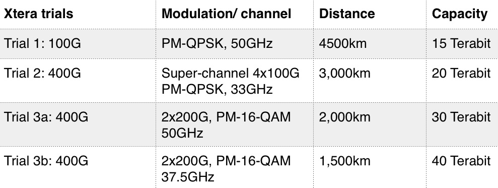 Table 1: Xtera's Verizon trial results using a 61nm spectrum and all-Raman amplification.
JDSU says hybrid amplification remains the most cost-competitive way to deliver the required OSNR and system capacity, while all-Raman can potentially increase system capacity.
Overall, it is network capacity and reach requirements that drive amplifier choice, says Krishnaswamy: "An overwhelming portion of WANs worldwide have adopted hybrid EDFA-Raman and this trend is expected to continue for the foreseeable future."
Meanwhile, the single channel micro-amp, sits alongside or is integrated within the transmitter. Operators want a transponder that meets various requirements for their reconfigurable networks. "If you look into the numbers, you want to boost the signal early on before it is attenuated," says II-VI's Hansen. "That gives you the best OSNR performance."
"This [single-channel amp] is a type that was rare in old systems," adds Finisar's Ghera. "It is also a market that is growing the fastest for us."
The micro-amp needs to be compact and low power, being alongside the power-hungry 100 Gig coherent transmitter. This is driving uncooled pump laser development and system integration.
Similar design goals apply to arrayed amplifiers that counter losses in ROADM add/ drop cards. "If you have some of the features of colourless, directionless and contentionless, you incur bigger losses in the node but you can make it up with other amps, one of these being arrayed amps," says Hansen.
Arrayed designs can have eight or more amps to support multiple-degree nodes so that achieving a power-efficient, compact design is paramount. Hence II-VI's development of an uncooled dual-chip pump laser integrated in a package. "Having four packages to pump eight amps in a small space that do not require cooling is a huge advantage," says Hansen.
The amplifier design challenges are set to continue.
One, highlighted by Infinera, is expanding amplification to the L-band to double overall capacity. JDSU highlights second-order and third-order Raman designs that use a more complex pump laser arrangement to improve system OSNR. Lowering the noise figure of EDFAs will be another continuing design goal, says JDSU.
II-VI expects further challenges in miniaturising single-channel and arrayed amplifier designs. Finisar also cites the need for more compact designs, citing putting an EDFA in an XFP package as an example.
Another challenge is producing high-power Raman amplifiers that can bridge extremely long spans, 300 to 400km. Such an amplifier must be able to read lots of physical parameters associated with the span and set the line accordingly, said Gheri.
II-VI's Hansen says the adoption of Raman and arrayed amplifiers is a good indicator of the wider deployment of next-generation network architectures. "Raman is a signature of the spread of 100 Gig but also the desire of being upgradable to higher bit rates," he says.
The article first appeared as an OFC 2014 show preview piece
Xtera demonstrates 40 Terabit using Raman amplification
- Xtera's Raman amplification boosts capacity and reach
- 40 Terabit optical transmission over 1,500km in Verizon trial
- 64 Terabit over 1,500km in 2015 using a Raman module operating over 100nm of spectrum
 Herve Fevrier
System vendor Xtera is using all these techniques as part of its Nu-Wave Optima system but also uses Raman amplification to extend capacity and reach.
"We offer capacity and reach using a technology - Raman amplification - that we have been pioneering and working on for 15 years," says Herve Fevrier, executive vice president and chief strategy officer at Xtera.
 The distributed amplification profile of Raman (blue) compared to an EDFA's point amplification. Source: Xtera
One way vendors are improving the amplification for 100 Gigabit and greater deployments is to use a hybrid EDFA/ Raman design. This benefits the amplifier's power efficiency and the overall transmission reach but the spectrum width is still dictated by Erbium to around 35nm. "And Raman only helps you have spans which are a bit longer," says Fevrier.
Meanwhile, Xtera is working on programable cards that will support the various transmission options. Xtera will offer a 100nm amplifier module this year that extends its system capacity to 24 Terabit (240, 100 Gig channels). Also planned this year is super-channel PM-QPSK implementation that will extend transmissions to 32 Terabit using the 100nm amplifier module. In 2015 Xtera will offer PM-16-QAM that will deliver the 48 Terabit over 2,000km and the 64 Terabit over 1,500km.
For Part 1, click here
ECOC 2013 review - Part 2
- Oclaro's Raman and hybrid amplifier platform for new networks
- MxN wavelength-selective switch from JDSU
- 200 Gigabit multi-vendor coherent demonstration
- Tunable SFP+ designs proliferate
- Finisar extends 40 Gigabit QSFP+ to 40km
- Oclaro’s tackles wireless backhaul with 2km SFP+ module
 Finisar's 40km 40 Gig QSFP+ demo. Source: Finisar
Amplifier market heats up
Oclaro detailed its high performance Raman and hybrid Raman/ Erbium-doped fibre amplifier platform. "The need for this platform is the high-capacity, high channel rates being installed [by operators] and the desire to be scalable - to support 400 Gig and Terabit super-channels in future," says Per Hansen, vice president of product marketing, optical networks solutions at Oclaro.
"Amplifiers are 'hot' again," says Daryl Inniss, vice president and practice leader components at market research firm, Ovum. For the last decade, amplifier vendors have been tasked with reducing the cost of their amplifier designs. "Now there is a need for new solutions that are more expensive," says Inniss. "It is no longer just cost-cutting."
Amplifiers are used in the network backbone to boost the optical signal-to-noise ratio (OSNR). Raman amplification provides significant noise improvement but it is not power efficient so a Raman amplifier is nearly always matched with an Erbium one. "You can think of the Raman as often working as a pre-amp, and the Erbium-doped fibre as the booster stage of the hybrid amplifier," says Hansen. System houses have different amplifier approaches and how they connect them in the field, while others build them on one card, but Raman/ Erbium-doped fibre are almost always used in tandem, says Hansen.
Oclaro provides Raman units and hybrid units that combine Raman with Erbium-doped fibre. "We can deliver both as a super-module that vendors integrate on their line cards or we can build the whole line card for them" says Hansen.
The Raman amplifier market is way bigger than people have forecast
Since Raman launches a lot of pump power into the fibre, it is vital to have low-loss connections that avoid attenuating the gain. "Raman is a little more sensitive to the quality of the connections and the fibre," says Hansen. Oclaro offers scan diagnostic features that characterise the fibre and determine whether it is safe to turn up the amplification.
"It can analyse the fibre and depending on how much customers want us to do, we can take this to the point that it [the design] can tell you what fibre it is and optimise the pump situation for the fibre," says Hansen. In other cases, the system vendors adopt their own amplifier control.
Oclaro says it is in discussion with customers about implementations. "We are shipping the first products based on this platform," says Hansen.
"[The] Raman [amplifier market] is way bigger than people have forecast," says Inniss. This is due to operators building long distance networks that are scalable to higher data rates. "Coherent transmission is the focal point here, as coherent provides the mechanism to go long distance at high data rates," says Ovum analyst, Inniss.
Wavelength-selective switches
JDSU discussed its wavelength-selective switch (WSS) products at ECOC. The company has previously detailed its twin 1x20 port WSS, which has moved from development to volume production.
At ECOC, JDSU detailed its work on a twin MxN WSS design. "It is a WSS that instead of being a 1xN - 1x20 or a 1x9 - it is an MxN," says Brandon Collings, chief technology officer, communications and commercial optical products at JDSU. "So it has multiple input and output ports on both sides." Such a design is used for the add and drop multiplexer for colourless and directionless reconfigurable optical add/ drop multiplexers (ROADMs).
"People have been able to build colourless and directionless architectures using conventional 1xN WSSes," says Collings. The MxN serves the same functionality but in a single integrated unit, halving the volume and cost for colourless and directionless compared to the current approach.
JDSU says it is also completing the development of a twin multicast switch, the add and drop multiplexer suited to colourless, directionless and contentionless ROADM designs.
200 Gigabit coherent demonstration
ClariPhy Communications, working with NeoPhotonics, Fujitsu Optical Components, u2t Photonics and Inphi, showcased a reference-design demonstration of 200 Gig coherent optical transmission using 16 quadrature amplitude modulation (16-QAM).
For the demonstration, ClariPhy provided the coherent silicon: the digital-to-analogue converter for transmission and the receiver analogue-to digital and digital signal processing (DSP) used to counter channel transmission impairments. NeoPhotonics provided the lasers, for transmission and at the receiver, u2t Photonics supplied the integrated coherent receiver, Fujistu Optical Components the lithium niobate nested modulator while Inphi provided the quad-modulator driver IC.
ClariPhy is developing a 28nm CMOS Lightspeed chip suited for metro and long-haul coherent transmission. The chip will support 100 and 200 Gigabit-per-second (Gbps) data rates and have an adjustable power consumption tailored to the application. The chip will also be suited for use within a coherent CFP module.
"All the components that we are talking about for 100 Gig are either ready or will soon be ready for 200 and 400 Gig," says Ferris Lipscomb, vice president of marketing at NeoPhotonics. To achieve 400Gbps, two 16-QAM channels can be used.
The DWDM market for 10 Gig is now starting to plateau
Tunable SFPs
JDSU first released a 10Gbps SFP+ optical module tunable across the C-band in 2012, a design that dissipates up to 2W. The SFP+ MSA agreement, however, calls for no greater than a 1.5W power consumption. "Our customers had to deal with that higher power dissipation which, in a lot of cases, was doable," says JDSU Collings.
 Robert Blum, Oclaro
JDSU's latest tunable SFP+ design now meets the 1.5W power specification. "This gets into the MSA standard's power dissipation envelop and can now go into every SFP+ socket that is deployed," says Collings. To achieve the power target involved a redesign of the tunable laser. The tunable SFP+ is now sampling and will be generally available one or two quarters hence.
Oclaro and Finisar also unveiled tunable SFP+ modules at ECOC 2013. "The design is using the integrated tunable laser and Mach-Zehnder modulator, all on the same chip," says Robert Blum, director of product marketing for Oclaro's photonic components.
Neither Oclaro nor Finisar detailed their SFP+'s power consumption. "The 1.5W is the standard people are trying to achieve and we are quite close to that," says Blum.
Both Oclaro's and Finisar's tunable SFP+ designs are sampling now.
Reducing a 10Gbps tunable transceiver to a SFP+ in effect is the end destination on the module roadmap. "The DWDM market for 10 Gig is now starting to plateau," says Rafik Ward, vice president of marketing at Finisar. "From an industry perspective, you will see more and more effort on higher data rates in future."
40G QSFP+ with a 40km reach
Finisar demonstrated a 40Gbps QSFP+ with a reach of 40km. "The QSFP has embedded itself as the form-factor of choice at 40 Gig," says Ward.
Until now there has been the 850nm 40GBASE-SR4 with a 100m reach and the 1310nm 40GBASE-LR4 at 10km. To achieve a 40km QSFP+, Finisar is using four uncooled distributed feedback (DFB) lasers and an avalanche photo-detector (APD) operating using coarse WDM (CWDM) wavelengths spaced around 1310nm. The QSFP+ is being used on client side cards for enterprise and telecom equipment, says Finisar.
Module for wireless backhaul
Oclaro announced an SFP+ that supports the wireless Common Public Radio Interface (CPRI) and Open Base Station Architecture Initiative (OBSAI) standards used to link equipment in a wireless cell's tower and the base station controller.
Until now, optical modules for CPRI have been the 10km 10GBASE-LR4 modules. "You have a relatively expensive device for the last mile which is the most cost sensitive [part of the network]," says Oclaro's Hansen.
Oclaro's 1W SFP+ reduces module cost by using a simpler Fabry-Perot laser but at the expense of a 2km reach only. However, this is sufficient for a majority of requirements, says Hansen. The SFP supports 2.5G, 3Gbps, 6Gbps and 10Gbps rates. "CPRI has been used mostly at 3 Gig and 6 Gig but there is interest in 10 Gig due to growing mobile data traffic and the adoption of LTE," says Hansen.
The SFP+ module is sampling and will be in volume production by year end.
For Part 1, click here
ROADMs and their evolving amplification needs
Technology briefing: ROADMs and amplifiers
Oclaro announced an add/drop routing platform at the recent OFC/NFOEC show. The company explains how the platform is driving new arrayed amplifier and pumping requirements.
 A ROADM comprising amplification, line-interfaces, add/ drop routing and transponders. Source: Oclaro
Agile optical networking is at least a decade-old aspiration of the telcos. Such networks promise operational flexibility and must be scalable to accommodate the relentless annual growth in network traffic. Now, technologies such as coherent optical transmission and reconfigurable optical add/drop multiplexers (ROADMs) have reached a maturity to enable the agile, mesh vision.
Coherent optical transmission at 100 Gigabit-per-second (Gbps) has become the base currency for long-haul networks and is moving to the metro. Meanwhile, ROADMs now have such attributes as colourless, directionless and contentionless (CDC). ROADMs are also being future-proofed to support flexible grid, where wavelengths of varying bandwidths are placed across the fibre's spectrum without adhering to a rigid grid.
Colourless and directionless refer to the ROADM's ability to transmit or drop any light path from any direction or degree at any network interface port. Contentionless adds further flexibility by supporting same-colour light paths at an add or a drop.
"You can't add and drop in existing architectures the same colour [light paths at the same wavelength] in different directions, or add the same colour from a given transponder bank," says Bimal Nayar, director, product marketing at Oclaro's optical network solutions business unit. "This is prompting interest in contentionless functionality."
The challenge for optical component makers is to develop cost-effective coherent and CDC-flexgrid ROADM technologies for agile networks. Operators want a core infrastructure with components and functionality that provide an upgrade path beyond 100 Gigabit coherent yet are sufficiently compact and low-power to minimise their operational expenditure.
ROADM architectures
ROADMs sit at the nodes of a mesh network. Four-degree nodes - the node's degree defined as the number of connections or fibre pairs it supports - are common while eight-degree is considered large.
The ROADM passes through light paths destined for other nodes - known as optical bypass - as well as adds or drops wavelengths at the node. Such add/drops can be rerouted traffic or provisioned new services.
Several components make up a ROADM: amplification, line-interfaces, add/drop routing and transponders (see diagram, above).
"With the move to high bit-rate systems, there is a need for low-noise amplification," says Nayar. "This is driving interest in Raman and Raman-EDFA (Erbium-doped fibre amplifier) hybrid amplification."
The line interface cards are used for incoming and outgoing signals in the different directions. Two architectures can be used: broadcast-and-select and route-and select.
With broadcast-and-select, incoming channels are routed in the various directions using a passive splitter that in effect makes copies the incoming signal. To route signals in the outgoing direction, a 1xN wavelength-selective switch (WSS) is used. "This configuration works best for low node-degree applications, when you have fewer connections, because the splitter losses are manageable," says Nayar.
For higher-degree node applications, the optical loss using splitters is a barrier. As a result, a WSS is also used for the incoming signals, resulting in the route-and-select architecture.
Signals from the line interface cards connect to the routing platform for the add/drop operations. "Because you have signals from any direction, you need not a 1xN WSS but an LxM one," says Nayar. "But these are complex to design because you need more than one switching plane." Such large LxM WSSes are in development but remain at the R&D stage.
Instead, a multicast switch can be used. These typically are sized 8x12 or 8x16 and are constructed using splitters and switches, either spliced or planar lightwave circuit (PLC) based .
"Because the multicast switch is using splitters, it has high loss," says Nayar. "That loss drives the need for amplification."

Add/drop platform
With an 8-degree-node CDC ROADM design, signals enter and exit from eight different directions. Some of these signals pass through the ROADM in transit to other nodes while others have channels added or dropped.
In the Oclaro design, an 8x16 multicast switch is used. "Using this [multicast switch] approach you are sharing the transponder bank [between the directions]," says Nayar.
 The 8-degree node showing the add/drop with two 8x16 multicast switches and the 16-transponder bank. Source: Oclaro
A particular channel is dropped at one of the switch's eight input ports and is amplified before being broadcast to all 16, 1x8 switches interfaced to the 16 transponders.
It is the 16, 1x8 switches that enable contentionless operation where the same 'coloured' channel is dropped to more than one coherent transponder. "In a traditional architecture there would only be one 'red' channel for example dropped as otherwise there would be [wavelength] contention," says Nayar.
The issue, says Oclaro, is that as more and more directions are supported, greater amplification is needed. "This is a concern for some, as amplifiers are associated with extra cost," says Nayar.
The amplifiers for the add/drop thus need to be compact and ideally uncooled. By not needing a thermo-electrical cooler, for example, the design is cheaper and consumes less power.
The design also needs to be future-proofed. The 8x16 add/ drop architecture supports 16 channels. If a 50GHz grid is used, the amplifier needs to deliver the pump power for a 16x50GHz or 800GHz bandwidth. But the adoption of flexible grid and super-channels, the channel bandwidths will be wider. "The amplifier pumps should be scalable," says Nayar. "As you move to super-channels, you want pumps that are able to deliver the pump power you need to amplify, say, 16 super-channels."
This has resulted in an industry debate among vendors as to the best amplifier pumping scheme for add/drop designs that support CDC and flexible grid.
EDFA pump approaches
Two schemes are being considered. One option is to use one high-power pump coupled to variable pump splitters that provides the required pumping to all the amplifiers. The other proposal is to use discrete, multiple pumps with a pump used for each EDFA.
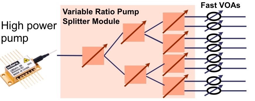 Source: Oclaro
In the first arrangement, the high-powered pump is followed by a variable ratio pump splitter module. The need to set different power levels at each amplifier is due to the different possible drop scenarios; one drop port may include all the channels that are fed to the 16 transponders, or each of the eight amplifiers may have two only. In the first case, all the pump power needs to go to the one amplifier; in the second the power is divided equally across all eight.
Oclaro says that while the high-power pump/ pump-splitter architecture looks more elegant, it has drawbacks. One is the pump splitter introduces an insertion loss of 2-3dB, resulting in the pump having to have twice the power solely to overcome the insertion loss.
The pump splitter is also controlled using a complex algorithm to set the required individual amp power levels. The splitter, being PLC-based, has a relatively slow switching time - some 1 millisecond. Yet transients that need to be suppressed can have durations of around 50 to 100 microseconds. This requires the addition of fast variable optical attenuators (VOAs) to the design that introduce their own insertion losses.
"This means that you need pumps in excess of 500mW, maybe even 750mW," says Nayar. "And these high-power pumps need to be temperature controlled." The PLC switches of the pump splitter are also temperature controlled.
The individual pump-per-amp approach, in contrast, in the form of arrayed amplifiers, is more appealing to implement and is the approach Oclaro is pursuing. These can be eight discrete pumps or four uncooled dual-chip pumps, for the 8-degree 8x16 multicast add/drop example, with each power level individually controlled.
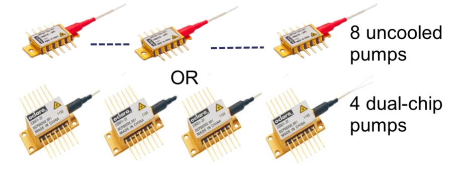 Source: Oclaro
Oclaro says that the economics favour the pump-per-amp architecture. Pumps are coming down in price due to the dramatic price erosion associated with growing volumes. In contrast, the pump split module is a specialist, lower volume device.
"We have been looking at the cost, the reliability and the form factor and have come to the conclusion that a discrete pumping solution is the better approach," says Nayar. "We have looked at some line card examples and we find that we can do, depending on a customer’s requirements, an amplified multicast switch that could be in a single slot."