Taking a unique angle to platform design

- A novel design based on a vertical line card shortens the trace length between an ASIC and pluggable modules.
- Reducing the trace length improves signal integrity while maintaining the merits of using pluggables.
- Using the vertical line card design will extend for at least two more generations the use of pluggables with Ethernet switches.
The travelling salesperson problem involves working out the shortest route on a round-trip to multiple cities. It’s a well-known complex optimisation problem.
Novel design that shortens the distance between an Ethernet switch chip and the front-panel optics
Systems engineers face their own complex optimisation problem just sending an electrical signal between two points, connecting an Ethernet switch chip to a pluggable optical module, for example.
Sending the high-speed signal over the link with sufficient fidelity for its recovery requires considerable electronic engineering design skills. And with each generation of electrical signalling, link distances are getting shorter.
In a paper presented at the recent ECOC show, held in Basel, consultant Chris Cole, working with Yamaichi Electronics, outlined a novel design that shortens the distance between an Ethernet switch chip and the front-panel optics.
The solution promises headroom for two more generations of high-speed pluggables. “It extends the pluggable paradigm very comfortably through the decade,” says Cole.
Since ECOC, there are plans to standardise the vertical line card technology in one or more multi-source agreements (MSAs), with multiple suppliers participating.
“This will include OSFP pluggable modules as well as QSFP and QSFP-DD modules,” says Cole.
Shortening links
Rather than the platform using stacked horizontal line cards as is common today, Cole and Yamaichi Electronics propose changing the cards’ orientation to the vertical plane.
Vertical line cards also enable the front-panel optical modules to be stacked on top of each other rather than side-by-side. As a result, the pluggables are closer to the switch ASIC; the furthest the high-speed electrical signalling must travel is three inches (7.6cm). The most distant span between the chip and the pluggable with current designs is typically nine inches (22.8cm).
“The reason nine inches is significant is that the loss is high as we reach 200 gigabits-per-second-per-lane and higher,” says Cole.
Current input-output proposals
The industry is pursuing several approaches to tackle such issues as the issues associated with high-speed electrical signalling and also input-output (I/O) bandwidth density.
One is to use twinaxial cabling instead of electrical traces on a printed circuit board (PCB). Such ‘Twinax’ cable has a lower loss, and its use avoids developing costly advanced-material PCBs.
Other approaches involve bringing the optics closer to the Ethernet switch chip, whether near-packaged optics or the optics and chip are co-packaged together. These approaches also promise higher bandwidth densities.
Cole’s talk focussed on a solution that continues using pluggable modules. Pluggable modules are a low-cost, mature technology that is easy to use and change.
However, besides the radio frequency (RF) challenges that arise from long electrical traces, the I/O density of pluggables is limited due to the size of the connector, while placing up to 36 pluggables on the 1 rack unit-high (1RU) front panel obstructs the airflow used for cooling.
Platform design
Ethernet switch chips double their capacity every two years. Their power consumption is also rising; Broadcom’s latest Tomahawk 5 consumes 500W.
The power supply a data centre can feed to each platform has an upper limit. It means fewer cards can be added to a platform if the power consumed per card continues to grow.
The average power dissipation per rack is 16kW, and the limit is around 32kW, says Cole. This refers to when air cooling is used, not liquid cooling.
He cites some examples.
A rack of Broadcom’s 12.8-terabit Tomahawk 3 switch chip – either with 32, 1RU or 16, 2RU cards with two chips per card – and associated pluggable optics consume over 30kW.
A 25.6-terabit Tomahawk 4-based chassis supports 16 line cards and consumes 28kW. However, using the recently announced Tomahawk 5, only eight cards can be supported, consuming 27KW.
“The takeaway is that rack densities are limited by power dissipation rather than the line card’s rack unit [measure],” says Cole.
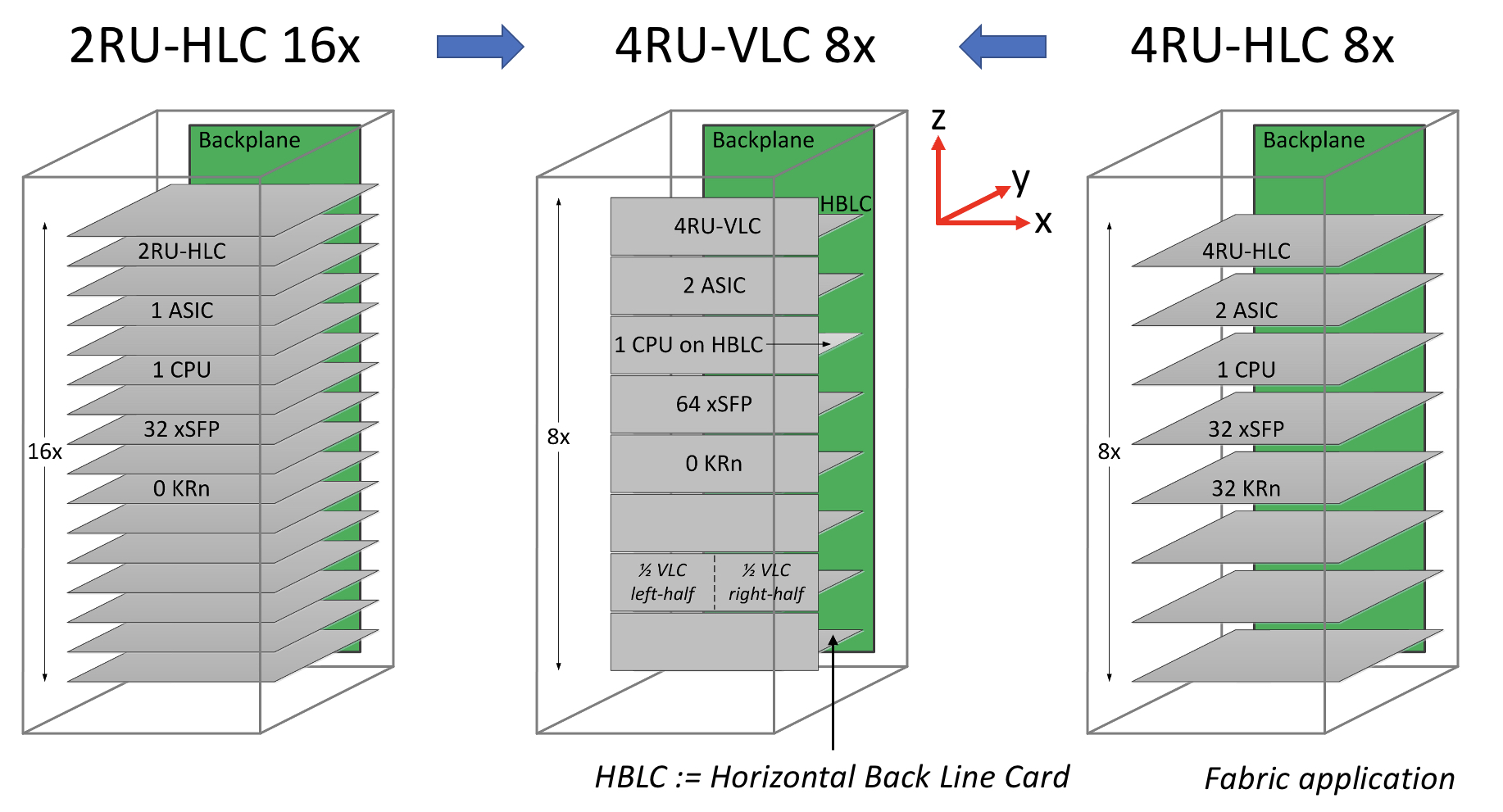
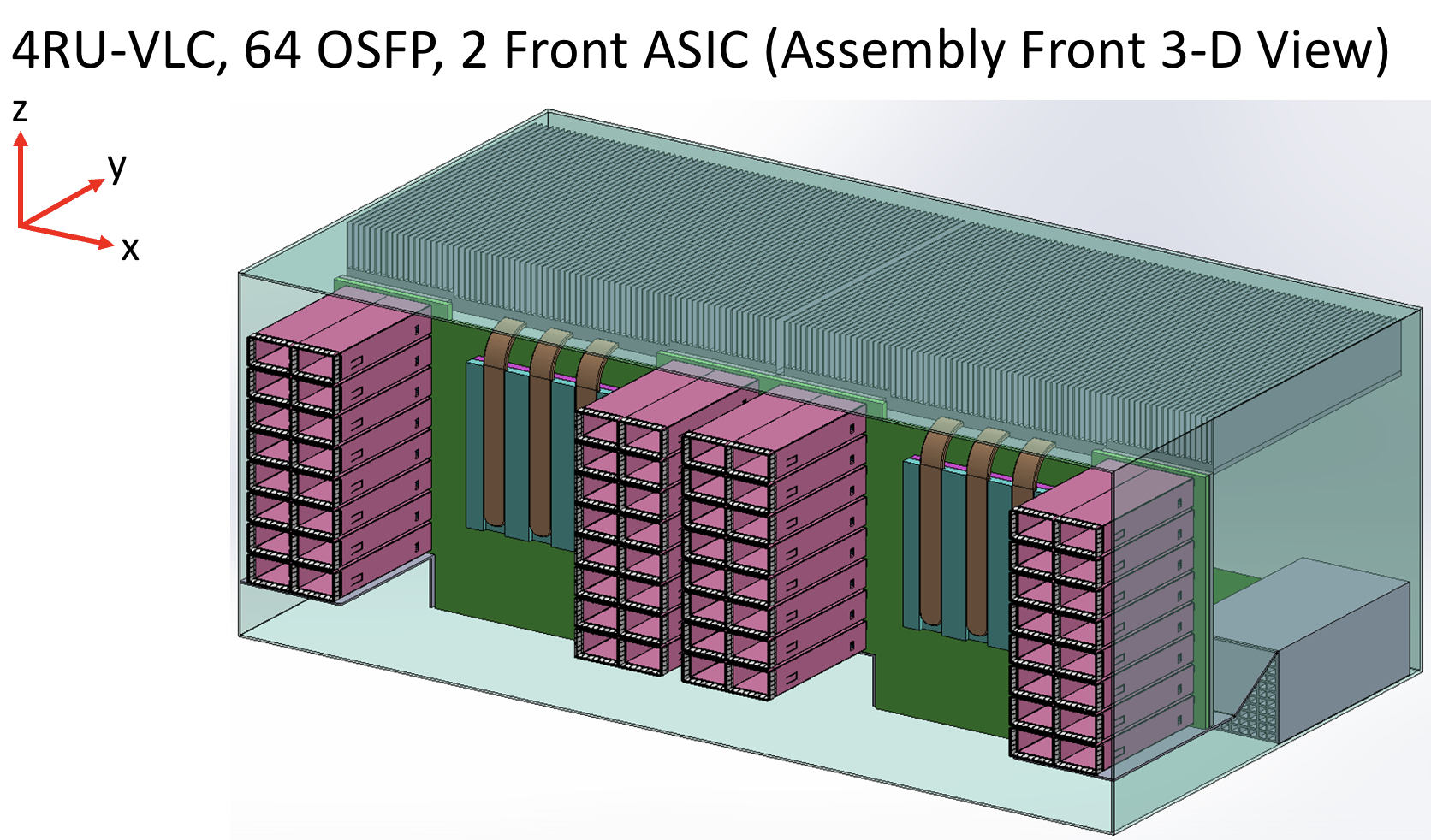
Vertical line card
The vertical line card design is 4RU high. Each card supports two ASICs on one side and 64 cages for the OSFP modules on the other.
A 32RU chassis can thus support eight vertical cards or 16 ASICs, equivalent to the chassis with 16 horizontal 2RU line cards.
The airflow for the ASICs is improved, enabling more moderate air fans to be used compared to 1RU or 2RU horizontal card chassis designs. There is also airflow across the modules.
“The key change in the architecture is the change from a horizontal card to a vertical card while maintaining the pluggable orientation,” says Cole.
As stated, the maximum distance between an ASIC and the pluggables is reduced to three inches, but Cole says the modules can be arranged around the ASIC to minimise the length to 2.5 inches.
Alternatively, if the height of the vertical card is an issue, a 3RU card can be used instead, which results in a maximum trace length of 3.5 inches. “[In this case], we don’t have dedicated air intakes for the CPU,” notes Cole.
Cole also mentioned the option of a 3RU vertical card that houses one ASIC and 64 OSFP modules. This would be suitable for the Tomahawk 5. However, here the maximum trace length is five inches.
Vertical connectors
Yamaichi Electronics has developed the vertical connectors needed to enable the design.
Cole points out that, unlike a horizontal connector, a vertical one uses equal-length contacts. This is not the case for a flat connector, resulting in performance degradation since a set of contacts has to turn and hence has a longer length.
Cole showed the simulated performance of an OSFP vertical connector with an insertion loss of over 70GHz.
“The loss up to 70GHz demonstrates the vertical connector advantage because it is low and flat for all the leads,” says Cole. “So this [design] is 200-gigabit ready.”
He also showed a vertical connector for the OSFP-XD with a similar insertion loss performance.
Also shown was a comparison with results published for Twinax cables. Cole says this indicates that the loss of a three-inch PCB trace is less than the loss of the cable.
“We’ve dramatically reduced the RF maximum length, so we had solved the RF roadblock problem, and we maintain the cost-benefit of horizontal line cards,” says Cole.
The I/O densities may be unchanged, but it preserves the mature technology’s benefits. “And then we get a dramatic improvement in cooling because there are no obstructions to airflow,” says Cole.
Vladimir Kozlov, CEO of the market research firm, LightCounting, wondered in a research note whether the vertical design is a distraction for the industry gearing up for co-packaged optics.
“Possibly, but all approaches for reducing power consumption on next-generation switches deserve to be tested now,” said Kozlov, adding that adopting co-packaged optics for Ethernet switches will take the rest of the decade.
“There is still time to look at the problem from all angles, literally,” said Kozlov

The future of optical I/O is more parallel links

Chris Cole has a lofty vantage point regarding how optical interfaces will likely evolve.
As well as being an adviser to the firm II-VI, Cole is Chair of the Continuous Wave-Wavelength Division Multiplexing (CW-WDM) multi-source agreement (MSA).
The CW-WDM MSA recently published its first specification document defining the wavelength grids for emerging applications that require eight, 16 or even 32 optical channels.
And if that wasn’t enough, Cole is also the Co-Chair of the OSFP MSA, which will standardise the OSFP-XD (XD standing for extra dense) 1.6-terabit pluggable form factor that will initially use 16, 100 gigabits-per-second (Gbps) electrical lanes. And when 200Gbps electrical input-output (I/O) technology is developed, OSFP-XD will become a 3.2-terabit module.
Directly interfacing with 100Gbps ASIC serialiser/ deserialiser (serdes) lanes means the 1.6-terabit module can support 51.2-terabit single rack unit (1RU) Ethernet switches without needing 200Gbps ASIC serdes required by eight-lane modules like the OSFP.
“You might argue that it [the OSFP-XD] is just postponing what the CW-WDM MSA is doing,” says Cole. “But I’d argue the opposite: if you fundamentally want to solve problems, you have to go parallel.”
CW-WDM specification
The CW-WDM MSA is tasked with specifying laser sources and the wavelength grids for use by higher wavelength count optical interfaces.
The lasers will operate in a subset of the O-band (1280nm-1320nm) building on work already done by the ITU-T and IEEE standards bodies for datacom optics.
In just over a year since its launch, the MSA has published Revision 1.0 of its technical specification document that defines the eight, 16 and 32 channels.
The importance of specifying the wavelengths is that lasers are the longest lead items, says Cole: “You have to qualify them, and it is expensive to develop more colors.”
In the last year, the MSA has confirmed there is indeed industry consensus regarding the wavelength grids chosen. The MSA has 11 promoter members that helped write the specification document and 35 observer status members.
“The aim was to get as many people on board as possible to make sure we are not doing something stupid,” says Cole.
As well as the wavelengths, the document addresses such issues as total power and wavelength accuracy.
Another issue raised is four-wavelength mixing. As the channel count increases, the wavelengths are spaced closer together. Four-wavelength mixing refers to an undesirable effect that impacts the link’s optical performance. It is a well-known effect in dense WDM transport systems where wavelengths are closely spaced but is less commonly encountered in datacom.
“The first standard is not a link budget specification, which would have included how much penalty you need to allocate, but we did flag the issue,” says Cole. “If we ever publish a link specification, it will include four-wavelength mixing penalty; it is one of those things that must be done correctly.”
Innovation
The MSA’s specification work is incomplete, and this is deliberate, says Cole.
“We are at the beginning of the technology, there are a lot of great ideas, but we are going to resist the temptation to write a complete standard,” he says.
Instead, the MSA will wait to see how the industry develops the technology and how the specification is used. Once there is greater clarity, more specification work will follow.
“It is a tricky balance,” says Cole. “If you don’t do enough, what is the value of it? But if you do too much, you inhibit innovation.”
“The key aspect of the MSA is to help drive compliance in an emerging market,” says Matt Sysak of Ayar Labs and editor of the MSA’s technical specification. “This is not yet standardised, so it is important to have a standard for any new technology, even if it is a loose one.”
The MSA wants to see what people build. “See which one of the grids gain traction,” says Sysak.
Ayar Labs’ SuperNova remote light source for co-packaged optics is one of the first products that is compliant with the CW-WDM MSA.
Sysak notes that at recent conferences co-packaged optics is a hot topic but what is evident is that it is more of a debate.
“The fact that the debate doesn’t seem to coagulate around particular specification definitions and industry standards is indicative of the fact that the entire industry is struggling here,” says Sysak.
This is why the CW-WDM MSA is important, to help promote economies of scale that will advance co-packaged optics.

Applications
Cole notes that, if anything, the industry has become more entrenched in the last year.
The Ethernet community is fixed on four-wavelength module designs. To be able to support such designs as module speeds increase, higher-order modulation schemes and more complex digital signal processors (DSPs) are needed.
“The problem right now is that all the money is going into signal processing: the analogue-to-digital converters and more powerful DSPs,” says Cole.
His belief is that parallelism is the right way to go, both in terms of more wavelengths and more fibers (physical channels).
“This won’t come from Ethernet but emerging applications like machine learning that are not tied to backward compatibility issues,” says Cole. “It is emerging applications that will drive innovation here.”
Cole adds that there is hyperscaler interest in optical channel parallelism. “There is absolutely a groundswell interest here,” says Cole. “This is not their main business right now, but they are looking at their long-term strategy.”
The likelihood is that laser companies will step in to develop the laser sources and then other companies will develop the communications gear.
“It will be driven by requirements of emerging applications,” says Cole. “This is where you will see the first deployments.”