
Relentless traffic growth leads to a ROADM rethink
Technology briefing: ROADMs
Lumentum has developed an optical switch to enable reconfigurable optical add-drop multiplexers (ROADMs) to cope with the traffic growth expected over the next decade.
The company’s MxN wavelength-selective switch (WSS) will replace the existing multicast switch used in colourless, directionless and contentionless ROADMs. The Lumentum TrueFlex 8x24 twin switch will enable networking nodes of 400-terabit capacity.
“This second-generation switch is what will take us into the 100 gigabaud and super-channel era of network scalability,” says Brandon Collings, CTO of Lumentum.
ROADMs
ROADMs sit at the mesh nodes in an optical network. Their function is to pass lightpaths destined for other nodes in the network - referred to as optical bypass - and enable the adding and dropping of wavelengths at the node. Such add/drops may be rerouted traffic or provisioned new services.
As network traffic continues to grow, so do the degrees of a ROADM and the ports of its sub-systems. The degree of a ROADM is defined to the number of connections or fibre pairs it can support. In the diagram, a ROADM of degree three is shown.
 A multicast switch-based 3-degree CDC ROADM. Source Lumentum.
It is rare to encounter more than five or six fibre routes leaving any given mesh node in a network, says Lumentum. “But in those fibre routes there is typically a large number of fibres - 64 or 128,” says Collings. “Operators deploy a conduit of fibre between cities.”
When the C-band fills up, an operator will light another fibre pair, taking up another of the ROADM’s degrees. ROADMs built today have 16 degrees. And since a fibre’s C-band can occupy some 30 terabits of data, this is how 400-terabit mesh nodes will be achieved.
“That is a pretty big node but that is the end [of life] capacity,” says Collings. “I don’t think you will find a 400-terabit node today but we build our networks so that they get there, five to eight years from when they are deployed.”
This raises another issue: the length of time it takes for any generational change of a ROADM design to take hold in the network.
“When a new approach comes along, it takes a couple of years for everyone to figure out how they will use it,” says Collings. Then, once a decision is made, it takes another two years to deploy followed by five to eight years before the ROADM node is filled.
“Nothing happens quickly in this business,” says Collings. “But the upside, from a business point of view, is that as things are designed in, they have a long deployment cycle.”
Lumentum illustrates the point with its own products.
The company is seeing growing demand for its dual TrueFlex WSS deployed in route-and-select ROADM architectures. “But we are still seeing growth on the older broadcast-and-select architectures underpinned by singe 1x9 WSSes,” says James Goodchild, director, product line management for wavelength management products at Lumentum.
CDC ROADMs
A colourless, directionless and contentionless (CDC) ROADM uses a twin multicast switch for the wavelength add and drop functions. The input fibre to each degree’s WSS is connected to the output path WSS of each of the ROADM’s other degrees. The input WSS also connects to the drop multicast switch (see diagram above).
Using a WSS on the input path means that only wavelengths of interest are routed to the WSS’ output ports. Hence the ROADM’s reference as a route-and-select architecture.
Using a 1xN splitter array instead of a WSS for the input path results in a broadcast-and-select ROADM. Here, the input fibre’s wavelengths are broadcast to all the N output ports. The high optical loss associated with the splitters is the main reason why CDC ROADM designs have transitioned to the WSS-based route-and-select architecture.
This second-generation switch is what will take us into the 100 gigabaud and super-channel era of network scalability
However, there is still an optical loss issue to be contended with, introduced by the add or drop multicast switch. Accordingly, along with the twin multicast switch are two arrays of erbium-doped fibre amplifiers (EDFAs). One EDFA array is on the drop ports to the MxN multicast switch and the second amplifier array boosts the outputs of the add-path multicast switch before their transmission into the network.
The MxN multicast switch comprises 1xN splitter arrays, N being the number of add-drop ports, and Mx1 selection switches where M is the number of directions the ROADM supports. A typical multicast switch is 8x16: eight being the ROADM’s number of directions and 16 the drop-port count.
Each of the N splitter arrays sends the signals on a drop port to all the Mx1 selection switches where each one pulls off the channel to be dropped. Having a selection switch at each of the multicast switch’s N drop ports is what enables contentionless operation, the avoidance of a collision when the same wavelength is droppedat a node from different degree directions.
MxN switch
Lumentum’s decision to develop the MxN switch to replace the multicast switch follows its study to understand how optical transmission networks will evolve with continual traffic growth.
One development is the adoption of higher-baud-rate, higher-capacity coherent transmissions that require wider channel widths. A 400-gigabit wavelength requires a 75GHz channel compared to the standard 50GHz fixed grid used for 100- and 200-gigabit transmissions. Future transmission speeds of 800 gigabits will use two such channels or 150GHz of spectrum, while a 1 terabit signal is expected to occupy 300GHz of fibre spectrum. “This is how we anticipate coherent transmission evolving,” says Collings.
Moving to wider channels also benefits the ROADM’s cost. If operators continued to use 50GHz channels, the channel count would grow exponentially with the growth in traffic. In contrast, adopting wider channels means the add-drop port count grows only linearly with traffic. “Using wider channels, the advantage is you don't have to support 600 ports of add-drop in your ROADM networks,” says Collings.
But wider channels means greater amplification demands on the EDFA arrays, an issue that will only worsen over time.
Multicast switch-based designs don’t support the wider channels we know are coming
Losing the amp
Because the power spectral density is constant, the power in a channel increases proportionally with its width. For example, a 75GHz channel has 2dB more power compared to a 50GHz channel spacing, a 150GHz channel 5dB more while a 300GHz channel has an extra 8dB.
The EDFA array is engineered to handle the worst case power requirement that occurs when all 16 optical transceivers into the multicast switch go to the same ROADM degree. Here the EDFA must be able to boost all 16 channels.
For a multicast switch with 16 ports, 22dBm amplification is needed for a 150GHz channel which requires going from an uncooled pump design to a cooled pump one. Equally, 25dBm amplification is needed for 300GHz channels. And as the number of degrees grows, so do the demands on the amplification until no practical amplifier design is possible (see diagram).
 The EDFA requirements to compensate for the optical loss of the multicast switch. The complexity of the EDFA design grows with the multicast switch's port count until it becomes insupportable. Source: Lumentum.
“This is not an issue today because we use very modest-sized channels and we engineer our systems to accommodate them,” says Collings. “But if you look forward, you realise they [multicast switch-based designs] don’t support the wider channels we know are coming.”
Using a WSS-based MxN switch solves this issue because, as with the input port WSS of a route-and-select architecture, the switch has a lower optical loss - under 8dB - compared to the 17dB of the splitter-based multicast switch.
The sub-8dB loss is below the threshold where amplification is needed: the optical signal is sufficiently strong at the drop port to be received, as are the added signals for transmission into the network. The resulting removal of the EDFAs simplifies greatly the complexity, size and cost of the CDC ROADM.
“The MxN is a WSS - it’s a router - so it sends all of the light in the direction it is supposed to go,” says Collings. “You can push through the MxN switch channels of any width and of any power because there is no amplifier that needs to be there and be designed appropriately."
The resulting second-generation CDC ROADM design is shown below.
 Source: Lumentum
Lumentum's Goodchild says the 8x24 twin implementation of the MxN switch will be available in the first quarter of 2019.
“Certain systems vendors already have access to samples,” says Goodchild.
Further reading
2D WSSes, click here
ROADMs and their evolving amplification needs, click here
Adding an extra dimension to ROADM designs
U.K. start-up ROADMap Systems, a developer of wavelength-selective switch technology, has completed a second round of funding. The amount is undisclosed but the start-up is believed to have raised several million dollars to date.
 Karl HeeksThe company will use the funding to develop a prototype of its two-dimensional (2D) optical beam-steering technique to integrate 24 wavelength-selective switches (WSSes) within a single platform.
The WSS is a key building block used within reconfigurable optical add-drop multiplexers (ROADMs).
The company’s WSS technology uses liquid crystal on silicon (LCOS) technology, the basis of existing WSS designs from the likes of Finisar and Lumentum. However, the start-up has developed a way to steer beams in 2D whereas current WSSes operate in a single dimension only.
The Cambridge-based company’s pre-production prototype will integrate 24,1x12 WSSes within a single package. The platform promises service providers ROADM designs that deliver space, power consumption and operational cost savings as well as systems advantages.
Wavelength-selective switch
A WSS takes wavelength-division multiplexed (WDM) channels from an input fibre and distributes them as required across an array of output fibres. Typical WSS configurations include a 1x9 - a one input fibre port and nine output ports - and a 1x20.
Current WSS designs comprise a diffraction grating, a cylindrical lens and an LCOS panel that is used to deflect the light channels to the required output fibres.
The diffraction grating separates the WDM channels while the cylindrical lens produces an elongated projection of the channels onto the LCOS device. The panel’s liquid crystals are oriented in such a way to direct the projected light channels to the appropriate output fibres. The orientation of the arrays of liquid crystals that perform the various steerings are holograms.
Commercial WSSes use the LCOS panel to steer in one dimension only: left or right. This means the output fibres are arranged in an array and the number of fibres is limited by the total deflection the LCOS can achieve. ROADMap Systems has developed a technique that produces holograms on the LCOS panel that steer light in two dimensions: left and right, up and down and diagonally.
Moreover, the holograms are confined to a small area of the panel, far fewer pixels than the elongated beams of a 1D WSS. Such confinement allows multiple light beams to be steered to the output fibre bundles.
“You use a much smaller area of the LCOS to bend things in 2D,” says Karl Heeks, CEO at ROADMap Systems.
Platform demonstrator
ROADMap System’s key intellectual property is its know-how to create the steering pattern - the hologram - programmed onto the LCOS panel.
The 2D WSS system requires calibration to create the precision holograms. The calibration data is generated during the device’s manufacture and forms the input to an algorithm that creates the holograms needed for the LCOS to steer accurately the traffic to the output fibres.
You use a much smaller area of the LCOS to bend things in 2D
ROADMap Systems has demonstrated its 2D steering technology to service providers, system vendors and optical subsystem players.
Now, the company is working to build the 24, 1x12 WSSs on an optical bench which it expects to complete by the year-end. The start-up is also creating the calibration software used for 2D beam steering as well as a user interface to allow networking staff to set up their required connections.
The first pre-production packaged systems – each one comprising a 4K LCOS panel and 312 fibres - are expected for delivery for trialling in 2019. The start-up is reluctant to give a firm date as it is still exploring design options. For example, ROADMap Systems has an improved lower-loss, more compact fibre coupling design but it has yet to decide whether to incorporate it or its existing design for its platform.
“We are not intending the prototype to go into a system within the network,” says Heeks. “It is more a vehicle to illustrate its capabilities.”
System benefits
The main benefit of ROADMap Systems’ 2D beam-steering WSS architecture is not so much its optical performance; the start-up expects its design to match the optical performance of existing 1D WSSes. Rather, there are architectural benefits besides the obvious integration and cost benefits of putting 24 WSSes in one platform.
The first system advantage is the ability to use the many WSSes to implement ROADMs of several degrees including the ROADM’s add-drop architecture. A two-degree ROADM handles east and west fibre pairs while a three-degree ROADM adds north-facing traffic as well.
 A ROADM architecture using 1xN splitters as part of the multicast switch. Source: ROADMap Systems.
To add and drop light-paths, a multicast switch is used (shown in green in the diagram above). The multicast switch can be implemented using optical splitters, however, due to their loss, optical amplifiers are needed to boost the signals, adding to the overall cost and system complexity.
WSSes can be used instead of the splitters as part of the multicast switch architecture such that optical amplification is not needed; the optical loss the WSS stage adds being much lower than the splitters. Removing optical amplification impacts significantly the overall ROADM cost (see diagram below).
 A ROADM architecture using 1xN WSSes as part of the multicast switch. Source: ROADMap Systems.
The integrated platform’s large number of WSSes will ease the implementation of the latest generation of ROADMs that are colourless, directionless and contentionless.
A colourless ROADM decouples the wavelength-dependency such that a light-path can be used on any of the network interface ports. Directionless refers to having full flexibility in the routeing of a light-path to any of the ports. Lastly, contentionless means non-blocking, where the same wavelength channel can be accommodated across all the degrees of the ROADM without contention.
And being LCOS-based, ROADMap’s WSSes also support a flexible grid enabling the ROADM to support channels such as coherent transmissions above 200 gigabit-per-second that do not conform to the rigid 50GHz-wide ITU grid spacings.
The second system advantage of the platform is that with its many WSSes, it can route and add-drop wavelengths across both the C and L-bands. However, the company is not planning to implement this feature in its preproduction prototype.
Next steps
ROADMap Systems says it is focussed on producing and testing its pre-production prototype. A further round of investment will be needed to turn the design into a commercial product.
“We believe that such a highly-integrated architecture will offer immediate performance and economic benefits to many teleccom applications,” says Heeks. “It is also well positioned for datacentre – DCI - applications where data needs to be routed between distributed datacentres linked by parallel fibres."
OFC 2015 digest: Part 1
- Several vendors announced CFP2 analogue coherent optics
- 5x7-inch coherent MSAs: from 40 Gig submarine and ultra-long haul to 400 Gig metro
- Dual micro-ITLAs, dual modulators and dual ICRs as vendors prepare for 400 Gig
- WDM-PON demonstration from ADVA Optical Networking and Oclaro
- More compact and modular ROADM building blocks
JDSU also showed a dual-carrier coherent lithium niobate modulator capable of 400 Gig for long-reach applications. The company is also sampling a dual 100 Gig micro-ICR also for multiple sub-channel applications.
Avago announced a micro-ITLA device using its external cavity laser that has a line-width less than 100kHz. The micro-ITLA is suited for 100 Gig PM-QPSK and 200 Gig 16-QAM modulation formats and supports a flex-grid or gridless architecture.

OFC 2014 product round-up - Part 1
Part 1: Line-side technologies
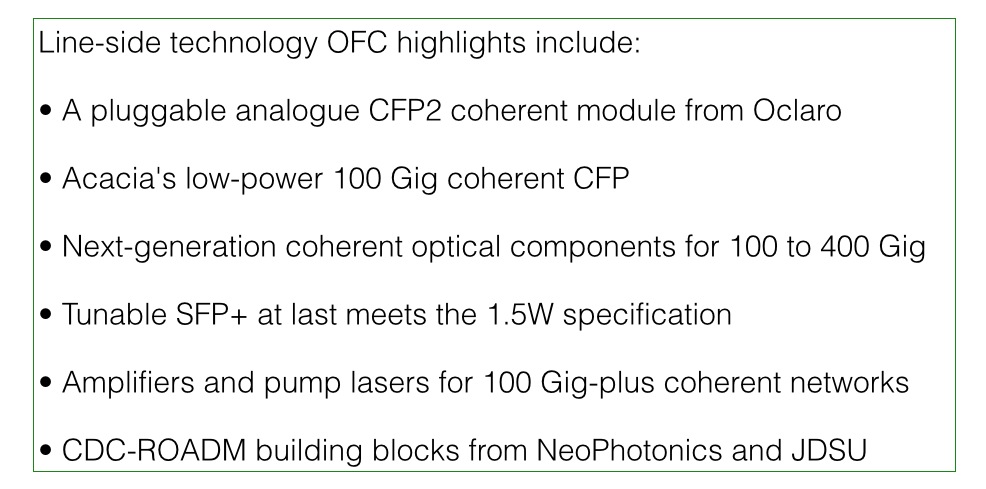
Technologies for 100 Gigabit were prominent at this year's OFC conference and exhibition held in San Francisco earlier this month.
The transition to smaller pluggable modules – client-side CFP2, CFP4 and QSFP28 interfaces - was one 100 Gig trend, another was the first 100 Gig pluggable modules for metro and metro-regional networks. Acacia Communications detailed its low-power AC-100 CFP, while Oclaro demonstrated coherent optics in the smaller CFP2 pluggable module.
To fit within the CFP2, Oclaro has developed a transmitter that combines two tunable lasers (one being for the coherent receiver) and an indium phosphide modulator, and a micro intradyne coherent receiver (micro ICR).
Having 100 Gig coherent optics in a CFP2 will enable equipment makers to double the 100 Gig line ports on their platforms. The optics will also support polarisation multiplexed, 16-quadrature amplitude modulation (PM-16-QAM) and hence 200 Gig transmission. However, given the CFP2's limited power profile, the coherent DSP-ASIC will need to reside on the line card, external to the module. Oclaro says samples of its 'analogue CFP2' will be with customers from the second quarter of the year.
The same coherent optics will also be used for Oclaro's 100 Gig coherent CFP module. "If you combine the [transmitter and micro ICR] optics, you get the CFP2, and the power target is 12W," says Robert Blum, director, product management, 40 and 100 Gig line-side modules at Oclaro. "Combining the optics with a [coherent] DSP in the CFP, the power target is 32W, the highest CFP [power] class."
Oclaro's 100 Gig CFP will be available by year-end, coinciding with a new generation of merchant coherent DSP-ASIC designs. ClariPhy Communications is sampling its LightSpeed-II devices, implemented using a 28nm CMOS process, while NTT Electronics (NEL) is developing its next-generation DSP-ASIC, expected to use an even more advanced CMOS process.
Integrating the DSP chip and optics in a CFP simplifies a line card design and adds flexibility: the same CFP port can be used for line-side or client-side modules. But given that the coherent optics consumes 12W, the next-generation DSP-ASIC must consume no more than 18W typically, with the remaining 2W to accommodate the physical layer ICs, if the CFP's maximum power profile is not to be exceeded.
Acacia Communications' AC-100 coherent CFP module uses the company's DSP-ASIC and photonic integrated circuit (PIC) implemented using silicon photonics. The resulting 100 Gig CFP consumes 24-26W, well within the CFP's maximum 32W.
Meanwhile, Fujitsu Optical Components demonstrated all the components needed to make a 100 Gig coherent CFP, using its indium phosphide modulator to generate a 100 Gig polarisation multiplexed, quadrature phase-shift keying (PM-QPSK) signal, and a micro ICR.
Considering that the 5x7-inch Optical Internetworking Forum (OIF) multi-source agreement (MSA) 100 Gig transponder for long-haul consumes some 80W, with the DSP-ASIC alone consuming over half that, the advent of the coherent CFP and analogue CFP2 highlights the industry’s recent progress in shrinking the size and power consumption of coherent optics.
"Our focus long term is the CFP2. It is where we think the market is going to go in the next two years."
Ferris Lipscomb, NeoPhotonics
Coherent components
NeoPhotonics detailed an integrated coherent transmitter that combines a narrow-linewidth tunable laser and a PM-QPSK modulator in one package. The device joins NeoPhotonics' micro Integrable Tunable Laser Assembly (ITLA) and micro ICR that have already been announced. "These are the next generation, smaller form factor coherent optical components," says Ferris Lipscomb, vice president of marketing at NeoPhotonics. The transmitter supports PM-QPSK and PM-16-QAM such that it can be used for 100, 200 and even as an element to enable 400 Gig transmission.
The device is suited for line card, OIF MSA modules, and pluggable CFP and CFP2 designs. "Our focus long term is the CFP2," says Lipscomb. "It is where we think the market is going to go in the next two years." NeoPhotonics says its coherent devices has been sampling to customers and will be generally available in the second half of the year.
Oclaro announced that its micro ITLA, first detailed at ECOC 2013, now supports a flexible grid; the tunable laser's wavelength can be set independent of the ITU Grid spanning the C-band. Such a capability is required for advanced optical networks based on flexible-grid ROADMs and spectrally-efficient super-channels. "The flexible-grid micro ITLA gives peace of mind [to operators] even if it is not widely used yet," says Oclaro's Blum. The technology used for the micro ITLA is also used for Oclaro's CFP and CFP2 line side modules.
Fujitsu Optical Components announced a lithium niobate modulator that supports 100 Gig PM-QPSK and 400 Gig PM-xQAM signals. The new modulator has the same drive voltage as its existing 100 Gig lithium niobate modulator but is half the size. The company also announced an accompanying ICR that also supports 100 and 400 Gig transmissions in core networks. The company says both devices will be available from July.
Sumitomo Electric Industries detailed its micro ITLA at OFC. The micro ITLA uses a narrower line width laser and reduces power consumption by a fifth. The company also showcased a micro ICR that supports 100 and 200 Gig transmissions, and an indium phosphide based Mach-Zehnder modulator that is smaller and has lower power than a lithium niobate-based version.
Avago Technologies announced its micro ICR at OFC, a demonstration of Avago's broad component portfolio following its acquisition of CyOptics. Finisar was another company that showcased a new portfolio of high-speed optical components following its acquisition of u2t Photonics. These include indium phosphide-based Mach-Zehnder modulators and 100 Gig receivers and photodetectors.
Tunable SFP+
Both JDSU and Oclaro detailed their latest 10 Gigabit tunable SFP+ optical modules. Moving the tunable laser design from an XFP to the SFP+ has been a challenge, meeting the SFP+'s smaller dimensions and 1.5W power consumption.
Oclaro's latest tunable SFP+ now meets the 1.5W SFP+ specification. Oclaro says that to achieve the specification, it produced a more compact integrated laser Mach-Zehnder chip. Oclaro demonstrated the tunable SFP+ operating at 85oC. Beta samples of the tunable SFP+ are being shipped and the module will soon undergo qualification.
JDSU has had a tunable SFP+ product for over a year but its power consumption is 2W. The SFP+ length is also elongated by 4mm to fit the tunable laser. Now, JDSU has announced a revised design that no longer needs the extra 4mm and achieves a power consumption of 1.6W. "We will achieve the 1.5W specification in the near future," says Brandon Collings, JDSU's CTO for communications and commercial optical products.
"The reason why there is a lot of talk about hybrid EDFA-Raman in the industry is that it works very well with coherent."
Rafik Ward, Finisar
Pump lasers and hybrid amplifiers
JDSU also announced pump laser designs. The motivation for these latest pump products is the more demanding link budgets required for 100 Gig-and-greater transmission speeds while still achieving long-distance reaches.
JDSU announced Raman pump lasers for hybrid EDFA-Raman amplifiers. These are more power-efficient and cover the Raman pump wavelengths required, says JDSU: a 600mW output between 1425-1470nm and 550mW at 1470-1495nm. The company has also detailed higher-power 980nm pumps for EDFAs. "More power is almost always a good thing as it allows you a lot more design freedom and performance in your amp," says Collings.
Finisar demonstrated a hybrid EDFA-Raman amplifier for the first time. The hybrid amp is capable of spanning 220km and has a 44dB link loss. "The reason why there is a lot of talk about hybrid EDFA-Raman in the industry is that it works very well with coherent," says Rafik Ward, vice president of marketing at Finisar. Amplifier span distances of 80km are commonly used but the purpose of the demonstration was to showcase the product's capability, says Ward.
WSSes and multicast switches
NeoPhotonics has announced a modular multicast switch that allows an operator to grow a ROADM's node according to demand. The multicast switch is used to add colourless, directionless and contentionless (CDC) attributes to the ROADM. "You can have any wavelength [colourless] from any direction come out at any port [directionless]," says Lipscomb. "And if you have two identical wavelengths coming from different directions, you can drop them through the same switch [contentionless]."
Lipscomb cites as an example an 8-degree ROADM node, with each direction fibre carrying 100 dense WDM channels. Even if only a quarter of the channels are dropped, that is 200 channels, he says: "What we are announcing is a modular multicast switch; you can start with 4 channels and 4 drops and keep adding modular line cards as needed to add more drop ports and more directions."
NeoPhotonics modular multicast switches include such dimensions as 4x4, 4x16 and 8x16. "Carriers don't want to limit their future deployment but they also don't want to spend a lot of money now because they might want to drop 100 channels later," says Lipscomb.
JDSU announced its second-generation twin 1x20 wavelength-selective switch (WSS) that fits on a single-slot card. The twin WSS is used for advanced flexible-grid CDC-ROADM nodes.
The latest twin 1x20 WSS has the same functionality as JDSU's current twin 1x20 WSS that has been available for a year but which occupies two chassis slots. "It has the same capability but is considerably smaller," says Collings.
Indeed, the twin WSS is sufficiently compact that other functions can be added to the card such as amplification, optical power monitoring and optical service channels, communication channels between nodes used for such tasks as provisioning, power management and firmware updates.
For the OFC 2014 product round-up - Part 2, click here
OFC/NFOEC 2012: Some of the exhibition highlights
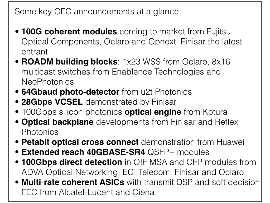
A round-up of some of the main announcements and demonstrations at the recent OFC/NFOEC 2012 exhibition and conference.
100 Gigabit coherent
Finisar demonstrated its first 100 Gigabit coherent receiver transponder. The 5x7inch dual-polarisation, quadrature phase-shift keying (DP-QPSK) module complies with the Optical Internetworking Forum's (OIF) multi-source specification. The companies joins Fujitsu Optical Components, Opnext and Oclaro that have already detailed their 100 Gigabit coherent modules. Since OFC/NFOEC, Oclaro and Opnext have announced their intention to merge.
"We can take off-the-shelf DSP technology and match it with vertically-integrated optics and come up with a module that is cost effective while enabling higher density for system vendors," says Rafik Ward, vice president of marketing at Finisar. "This will start the shift away from the system vendors' proprietary line cards."
Opnext announced it has demonstrated interoperability between its OMT-100 100 Gigabit-per-second (Gbps) coherent module and 100 Gigabit systems from Fujitsu Optical Systems and NEC. All three designs use NTT Electronics' (NEL) DSP-ASIC coherent receiver chip. "For those that use the same NEL modem chip, we can interoperate with each other," says Ross Saunders, general manager, next-generation transport for Opnext Subsystems.

They come back to folks like us and say: 'If you can hit this price point, then we will use you'
Ross Saunders, Opnext
Oclaro's MI 8000XM 100Gbps module also uses the NEL DSP-ASIC but was not part of the interoperability test sponsored by Japanese operator, NTT.
Oclaro announced its 100Gbps coherent module is now being manufactured using all its own optical components. These include a micro integrated tunable laser assembly (ITLA) - the latest ratified MSA that is more compact and has a higher output power, its modulator and its coherent receiver module.
Using its components enables the company to control performance-cost tradeoffs, says Per Hansen, vice president of product marketing, optical networks solutions at Oclaro: "This [vertical integration] gives us a flexibility we didn’t have in the past."
Finisar is not saying which merchant DSP-ASIC it is using. But like the NEL device, the DSP-ASIC supports soft-decision forward error correction (SD-FEC) to achieve a reach of over 2,000km.
Meanwhile, the module makers' 100Gbps modules are starting to be shipped to customers.
"We shipped [samples] to four customers last quarter and we are probably going to ship to another four or five by the end of this quarter," says Opnext's Saunders.
Opnext says nearly all of its early customers do not have their own in-house 100Gbps developments. However, the systems vendors that have internal 100Gbps programmes have designed their line cards using the same 168-pin interface. This allows them to replace their own 100Gbps daughter cards with a merchant 5x7-inch module.
 "This [vertical integration] gives us a flexibility we didn’t have in the past."
Per Hansen, Oclaro
The company also announced its OTS-100FLX 100Gbps muxponder, transponder and regenerator line cards that use the OTM-100 module and which slot into its OTS-4000 chassis. The chassis supports eight 100Gbps cards. Opnext's smaller 4RU OTS-mini platform hosts two 100Gbps line cards, mounted horizontally. Over half of Opnext's revenues are from subsystems sales which it brands and sells to system vendors.
As for the other 100Gbps transponder makers, Oclaro is sending out its first module samples now. Finisar says its module will be generally available by the year-end, while Fujitsu Optical Components' module was released in April.
Optical components for 200Gbps DP-QPSK
u2t Photonics announced its latest 64Gbaud photo-detector that points to the next speed shift in line-side transmission. The photo-detector is one key building block to the eventual development of a single-carrier DP-QPSK capable of 200Gbps or using 16-QAM, 400Gbps.

"We can already support the higher interface speed and data throughput"
Jens Fiedler, u2t Photonics
"System companies are looking for two things: to increase the baud rate and to use more complex modulation schemes," says Jens Fiedler, vice president sales and marketing at u2t Photonics. "[With this announcement] from the optical component perspective, we can already support the higher interface speed and data throughput."
1x23 Wavelength-selective switch
Oclaro announced a 1x23 wavelength selective switch at OFC. According to Oclaro, the 1x23 WSS has come about due to the operators' desire to support 12-degree nodes: an input port (1 degree) and through-connections on 11 other ports. The remaining 12 [of the WSS's 24 ports] are used as drop ports.
"If for each of those ports you have a fan-out that is steerable to 8 ports, you have 12x8 or 96 as the total channels you can support for a full add-drop," says Hansen. Such a 12-degree, 96-channel requirement was set by operators early on, or at least it was an industry desire, says Hansen.
Switching elements that address these drop requirements - multicast switches - were announced by NeoPhotonics and Enablence Technologies at OFC. The switches, planar lightwave circuit (PLC) hybrid integration designs, implement 8x16 multicast switches.
"The multicast switch takes signals from eight different inputs - 8 different directions in a ROADMs node and distributes those signals to up to 16 drop ports," says Ferris Lipscomb, vice president of marketing at NeoPhotonics.
Such PLC designs are complex, comprising power splitters, waveguide switching, variable optical attenuators and photo-detectors for channel monitoring.
According to NeoPhotonics, the number of optical functions used to implement the multicast switch is in the hundreds.
Enablence already has 8x8 and 8x12 multicast switches and has launched its 8x16 device. Although the company is a hybrid PIC specialist and has PLC technology, it uses polymer PLCs for the multicast designs, claiming they are lower power. NEL is another company offering 8x8 and 8x12 multicast switches.
Passive optical networking
Finisar also demonstrated a mini-PON network, highlighting its optical line terminal (OLT) transceivers, splitters and its latest GPON-stick, an GPON optical network unit built into an SFP. The demo involved using the ONU SFP transceiver in an Ethernet switch port as part of a PON network to deliver high-definition video and audio from the OLT to a high-definition TV.
The company also introduced two splitter products a 1:128 port splitter and a 2:64 (used for redundancy). These high-split ratios are being prepared for the advent of 10 Gigabit PON.
Enablence also demonstrated a WDM-PON 32-channel receiver module at OFC. "It takes 32 TO-can receivers and replaces them with a small module which includes the AWG (arrayed waveguide grating demultiplexer) and the 32 receivers," says Matt Pearson, vice president, technology, optical components division at Enablence Technologies. The design promises to increase system density by fitting two such receivers on a single blade.
Optical engines
Silicon photonics firm, Kotura, detailed its 100Gbps optical engine chip, implemented as a 4x25Gbps design. The optical engine consumes 5W and has a reach of at least 10km, making it suitable for requirements in the data centre including the 100 Gigabit Ethernet IEEE 100GBASE-LR4 standard.

"The 100Gbps chip - 5mmx6mm - is small enough to fit in the QSFP+ and emerging CFP4 optical modules
Arlon Martin, Kotura
Kotura demonstrated to select customers its optical engine. "We are not announcing the product yet," says Arlon Martin, vice president of marketing at Kotura.
Optical engines are used in several applications: pluggable modules on a system's face-plate, the optics at each end of an active optical cable, and for board-mounted embedded applications.
For embedded applications, the optical engine is mounted deeper within the line card, close to high-speed chips, for example, with the signals routed over fibre to the face-plate connector. Using optics rather than high-speed copper traces simplifies the printed circuit board design.Embedded optical engines will also be used for optical backplane-based platforms.
Kotura's silicon photonics-based optical engine integrates all the functions needed for the transmitter and receiver on-chip. These include the 25Gbps optical modulators and drivers, the 4:1 multiplexer and 1:4 demultiplexer and four photo-detectors. To create the lasers, an array of four gain blocks are coupled to the chip. Each of laser's wavelength, around 1550nm, is set using on-chip gratings.
The 100Gbps chip, measuring about 5mmx6mm, is small enough to fit in the QSFP+ and emerging CFP4 optical modules, says Martin. The QSFP+ is likely to be the first application for Kotura's 100Gbps optical engine, used to connect switches within the data centre.
Finisar demonstrated its own VCSEL-based board mount optical assembly - also an optical engine - to highlight the use of the technology for future optical backplanes.
The demonstration, involving Vario-optics and Huber + Suhner, included boards in a chassis. The board includes the optical engine coupled to polymer waveguides from Vario-optics which connect it to a backplane connector, built by Huber + Suhner. "The idea is to show what an integrated optical chassis will look like," says Ward.
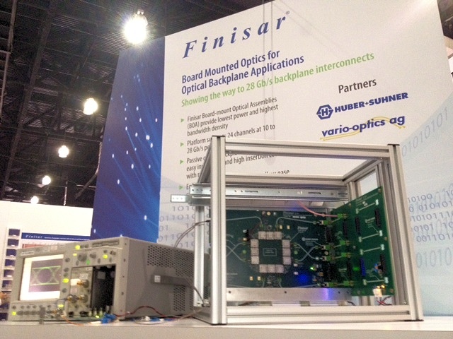 Finisar's optical backplane demo using board-mounted optics. Source: Finisar
The optical engine comprises 24 channels - 12 transmitters at 10Gbps and 12 receivers in a single board-mounted package. The optics can operate at 10, 12, 14, 25 and 28Gbps, says Finisar. The connector allows the optical engines on different cards to interface via the waveguides. The advantage of polymer waveguides is that they are relatively easy to etch on printed circuit boards and since they replace fibre, they remove fibre management issues. However the technology needs to be proven before system vendors will use such waveguides as standard in their platforms.
Interconnect specialist Reflex Photonics demonstrated an 8.6Tbps optical backplane at OFC. The demonstrator uses Reflex's LightABLE optical engines to implement 864 point-to-point optical fibre links to achieve 8.6Tbps in a single chassis.
The optical fabric comprises six layers of 12x12 fully connected broadcast meshes. Each line card supports 720Gbps into the optical backplane and 60Gbps direct bandwidth between any two cards.
32G Fibre channel
Finisar also highlighted its 28Gbps VCSEL that will be used for the 32 Gigabit Fibre Channel standard. The actual line rate for 32Gbps Fibre Channel is 28.05Gbps. The VCSEL is packaged into a transmitter optical sub-assembly (TOSA) that fits inside a SFP+ module.
"We view 28Gbps VCSEL as strategic due to all the applications it will enable," says Ward.
Besides 32Gbps Fibre Channel, the high-speed VCSEL is suited for the next Infiniband data rate - enhanced data rate (EDR) at 4x25Gbps or 12x25Gbps. There is also standards work in the IEEE for a new 100Gbps Ethernet standard that can use 4x25Gbps VCSELs.
Further reading:
Gazettabyte's full OFC NFOEC 2012 coverage
LightCounting: Notes from OFC 2012: Onset of the Terabit Age
Ovum's OFC coverage