
New MSA to enable four-lambda 400-gigabit modules
A new 100-gigabit single-wavelength multi-source agreement (MSA) has been created to provide the industry with 2km and 10km 100-gigabit and 400-gigabit four-wavelength interfaces.
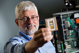
 Mark NowellThe MSA is backed by 22 founding companies including Microsoft, Alibaba and Cisco Systems.
The initiative started work two months ago and a draft specification is expected before the year end.
“Twenty-two companies is a very large MSA at this stage, which shows the strong interest in this technology,” says Mark Nowell, distinguished engineer, data centre switching at Cisco Systems and co-chair of the 100G Lambda MSA. “It is clear this is going to be the workhorse technology for the industry for quite a while.”
Phased approach
The 100G Lambda MSA is a phased project. In the first phase, three single-mode fibre optical interfaces will be specified: a 100-gigabit 2km link (100G-FR), a 100-gigabit 10km link (100G-LR), and a 2km 400-gigabit coarse wavelength-division multiplexed (CWDM) design, known as the 400G-FR4. A 10km version of the 400-gigabit CWDM design (400G-LR4) will be developed in the second phase.
For the specifications, the MSA will use work already done by the IEEE that has defined two 100-gigabit-per-wavelength specifications. The IEEE 802.3bs 400 Gigabit Ethernet Task Force has defined a 400-gigabit parallel fibre interface over 500m, referred to as DR4 (400GBASE-DR4). The second, the work of the IEEE 802.3cd 50, 100 and 200 Gigabit Ethernet Task Force, defines the DR (100GBASE-DR), a 100-gigabit single lane specification for 500m.
Twenty-two companies is a very large MSA at this stage, which shows the strong interest in this technology
“The data rate is known, the type of forward-error correction is the same, and we have a starting point with the DR specs - we know what their transmit levels and receive levels are,” says Nowell. The new MSA will need to contend with the extra signal loss to extend the link distances to 2km and 10km.
With the 2km 400G-FR4 specification, not only does the design involve longer distances but also loss introduced using an optical multiplexer and demultiplexer to combine and separate the four wavelengths transmitted over the single-mode fibre.
“It is really a technical problem, one of partitioning the specifications to account for the extra loss of the link channel,” says Nowell.
One way to address the additional loss is to increase the transmitter’s laser power but that raises the design’s overall power consumption. And since the industry continually improves receiver performance - its sensitivity - over time, any decision to raise the transmitter power needs careful consideration. “There is always a trade off,” says Nowell. “You don't want to put too much power on the transmitter because you can’t change that specification.”
The MSA will need to decide whether the transmitter power is increased or is kept the same and then the focus will turn to the receiver technology. “This is where a lot of the hard work occurs,” he says.
Origins
The MSA came about after the IEEE 802.3bs 400 Gigabit Ethernet Task Force defined 2km (400GBASE-FR8) and 10km (400GBASE-LR8 interfaces based on eight 50 gigabit-per-second wavelengths. “There was concern or skepticism that some of the IEEE specification for 2km and 10km at 400 gigabits were going to be the lowest cost,” says Nowell. Issues include fitting eight wavelengths within the modules as well as the cost of eight lasers. Many of the large cloud players wanted a four-wavelength solution and they wanted it specified.
The debate then turned to whether to get the work done within the IEEE or to create an MSA. Given the urgency that the industry wanted such a specification, there was a concern that it might take too long to get the project started and completed using an IEEE framework, so the decision was made to create the MSA.
“The aim is to write these specifications as quickly as we can but with the assumption that the IEEE will pick up the challenge of taking on the same scope,” says Nowell. “So the specs are planned to be written following IEEE methodology.” That way, when the IEEE does address this, it will have work it can reference.
“We are not saying that the MSA spec will go into the IEEE,” says Nowell. “We are just making it so that the IEEE, if they chose, can quickly and easily have a very good starting point.”
Form factors
The MSA specification does not dictate the modules to be used when implementing the 100-gigabit-based wavelength designs. An obvious candidate for the single-wavelength 2km and 10km designs is the SFP-DD. And Nowell says the OSFP and the QSFP-DD pluggable optical modules as well as COBO, the embedded optics specification, will be used to implement 400G-FR4. “From Cisco’s point of view, we believe the QSFP-DD is where it is going to get most of its traction,” says Nowell, who is also co-chair of the QSFP-DD MSA.
Nowell points out that the industry knows how to build systems using the QSFP form factors: how the systems are cooled and how the high-speed tracks are laid down. The development of the QSFP-DD enables the industry to reuse this experience to build new high-density systems.
“And the backward compatibility of the QSFP-DD is massively important,” he says. A QSFP-DD port also supports the QSFP28 and QSFP modules. Nowell says there are customers that buy the latest 100-gigabit switches but use lower-speed 40-gigabit QSFP modules until their network needs 100 gigabits. “We have customers that say they want to do the same thing with 100 and 400 gigabits,” says Nowell. “That is what motivated us to solve that backward-compatibility problem.”
Roadmap
A draft specification of the phase one work will be published by the 22 founding companies this year. Once published, other companies - ‘contributors’ - will join and add their comments and requirements. Further refinement will then be needed before the final MSA specification, expected by mid-2018. Meanwhile, the development of the 10km 400G-LR4 interface will start during the first half of 2018.
The MSA work is focussed on developing the 100-gigabit and 400-gigabit specifications. But Nowell says the work will help set up what comes next after 400 gigabits, whether that is 800 gigabits, one terabit or whatever.
“Once a technology gets widely adopted, you get a lot of maturity around it,” he says. “A lot of knowledge about where and how it can be extended.”
There are now optical module makers building eight-wavelength optical solutions while in the IEEE there are developments to start 100-gigabit electrical interfaces, he says: “There are a lot of pieces out there that are lining up.”
The 22 founding members of the 100G Lambda MSA Group are: Alibaba, Arista Networks, Broadcom, Ciena, Cisco, Finisar, Foxconn Interconnect Technology, Inphi, Intel, Juniper Networks, Lumentum, Luxtera, MACOM, MaxLinear, Microsoft, Molex, NeoPhotonics, Nokia, Oclaro, Semtech, Source Photonics and Sumitomo Electric.
Creating a long-term view for the semiconductor industry
The semiconductor industry is set for considerable change over the next 15 years.
“We are at an inflection point in the history of the [chip] industry,” says Thomas Conte, an IEEE Fellow. “It will be very different and very diverse; there won’t be one semiconductor industry.”
Conte (pictured) is co-chair of the IEEE Rebooting Computing initiative that is sponsoring the International Roadmap of Devices and Systems (IRDS) programme (See The emergence of the IRDS, below). The IRDS is defining technology roadmaps over a 15-year horizon and in November will publish its first that spans nine focus areas.
The focus of the IRDS on systems and devices and the broadening of technologies being considered is a consequence of the changing dynamics of the chip industry.
Conte stresses that it is not so much the ending of Moore’s Law that is causing the change as the ending of CMOS. Transistors will still continue to shrink even though it is becoming harder and costlier to achieve but the scaling benefits that for decades delivered a constant power density for chips with each new CMOS process node ended a decade ago.
“Back in the day it was pretty easy to plot it [the roadmap] because the technology was rather static in what we wanted to achieve,” says Conte. That ‘cushy ride’ that CMOS has delivered is ending. “The question now is: Are there other technologies we should be investing in that help applications move forward?” says Conte.
Focus groups
The IRDS has set up nine focus groups and in March published the first white papers from the teams.
The most complete white paper is from the More Moore focus group which looks at how new generations of smaller transistor features will be achieved. “It is clear that for the next 10 to 15 years we still have a lot of CMOS nodes left,” says Conte. “We still have to track what happens to CMOS.”
Conte says it is becoming clearer that ICs, in general, are going to follow the course of flash memory and be constructed as 3D monolithic designs. “We are just beginning to understand how to do this," says Conte.
"This does not mean we are going to get transistors that make computing faster without doing something different,” he says. This explains the work of the Beyond CMOS (Emerging Research Devices) focus team that is looking at alternative non-CMOS technologies to advance systems performance.
It is clear that for the next 10 to 15 years we still have a lot of CMOS nodes left
A third IRDS focus group is Outside System Connectivity which includes interface technologies such as photonic interconnect needed for future systems. “Outside System Interconnect is an important focus group and it is also our interface to the IEEE 5G roadmap team,” he says.
Conte also highlights two other IRDS focus teams: System and Architecture, and Applications Benchmarking. “These two focus teams are really important as to what the IRDS is all about,” says Conte.
The System and Architecture group has identified four systems views that it will focus on: the data centre, mobile handsets and tablets, edge devices for the Internet of Things, and control systems for the cyber-physical world such as automation, robotics and automotive systems.
The Application Benchmarking focus group is tasked with predicting key applications, quantifying how their performance is evolving and identifying roadblocks that could hinder their progress. Feature recognition, an important machine learning task, is one such example.
The IRDS is also continuing the working format established by the ITRS whereby every odd year a new 15-year roadmap is published while updates are published every even year.
Roadmapping
Three communities contribute to the development of the IRDS roadmap: industry, government and academia.
Industry is more concerned with solving their immediate problems and do not have the time or resources to investigate something that might or might not work in 15 years’ time, says Conte. Academia, in contrast, is more interested in addressing challenging problems over a longer term, 15-year horizon. Government national labs in the US and Europe’s imec sit somewhere in between and try to come up with mid-range solutions. “It is an interesting tension and it seems to work,” says Conte.
Contributors to the IRDS are from the US, Europe, Japan, South Korea and Taiwan but not China which is putting huge effort to be self-sufficient in semiconductors.
“We have not got participation for China yet,” says Conte. “It is not that we are against that, we just have not made the connections yet.” Conte believes China’s input would be very good for the roadmap effort. “They are being very aggressive and bright and they are more willing to take risks than the West,” he says.
What will be deemed a success for the IRDS work?
“It is to come up with a good prediction that is 15 years out and identify what the roadblocks are to getting there.”
____________________________________________________________
The emergence of the IRDS
The IRDS was established in 2016 by the IEEE after it took over the roadmap work of the International Technology Roadmap for Semiconductors (ITRS), an organisation sponsored by the five leading chip manufacturing regions in the world.
“The [work of the] ITRS was a bottoms-up roadmap, driven by the semiconductor industry,” says Conte. “It started with devices and didn't really go much higher.”
With the end of scaling, whereby the power density of chips remained constant with each new CMOS process node, the ITRS realised its long-established roadmap work needed a rethink which resulted in the establishment of ITRS 2.0.
“The ITRS 2.0 was an attempt to do a top-down approach looking at the system level and working down to devices,” says Conte. It was well received by everyone but the sponsors, says Conte, which was not surprising given their bottoms-up focus. It resulted in the sponsors of the ITRS 2.0 such as the US Semiconductor Industry Association (SIA) pulling out and the IEEE stepping in.
“This is much closer to what we are trying to do with the Rebooting Computing so it makes sense this group comes into the IEEE band and we act as a sponsor,” says Conte.
Reporting the optical component & module industry
LightCounting recently published its six-monthly optical market research covering telecom and datacom. Gazettabyte interviewed Vladimir Kozlov, CEO of LightCounting, about the findings.
When people forecast they always make a mistake on the timeline because they overestimate the impact of new technology in the short term and underestimate in the long term
Q: How would you summarise the state of the optical component and module industry?
VK: At a high level, the telecom market is flat, even hibernating, while datacom is exceeding our expectations. In datacom, it is not only 40 and 100 Gig but 10 Gig is growing faster than anticipated. Shipments of 10 Gigabit Ethernet (GbE) [modules] will exceed 1GbE this year.
The primary reason is data centre connectivity - the 'spine and leaf' switch architecture that requires a lot more connections between the racks and the aggregation switch - that is increasing demand. I suspect it is more than just data centres, however. I wouldn't be surprised if enterprises are adopting 10GbE because it is now inexpensive. Service providers offer Ethernet as an access line and use it for mobile backhaul.
Can you explain what is causing the flat telecom market?
Part of the telecom 'hibernation' story is the rapidly declining SONET/SDH market. The decline has been expected but in fact it had been growing up till as recently as two years ago. First, 40 Gigabit OC-768 declined and then the second nail in the coffin was the decline in 10 Gig sales: 10GbE is all SFP+ whereas 0C-192 SONET/SDH is still in the XFP form factor.
The steady dense WDM module market and the growth in wireless backhaul are compensating for the decline in SONET/SDH market as well as the sharp drop this year in FTTx transceiver and BOSA (bidirectional optical sub assembly) shipments, and there is a big shift from transceivers to BOSAs.
LightCounting highlights strong growth of 100G DWDM in 2013, with some 40,000 line card port shipments expected this year. Yet LightCounting is cautious about 100 Gig deployments. Why the caution?
We have to be cautious, given past history with 10 Gig and 40 Gig rollouts.
If you look at 10 Gig deployments, before the optical bubble (1999-2000) there was huge expected demand before the market returned to normality, supporting real traffic demand. Whatever 10 Gig was installed in 1999-2000 was more than enough till 2005. In 2006 and 2007 10 Gig picked up again, followed by 40 Gig which reached 20,000 ports in 2008. But then the financial crisis occurred and the 40 Gig story was interrupted in 2009, only picking up from 2010 to reach 70,000 ports this year.
So 40 Gig volumes are higher than 100 Gig but we haven't seen any 40 Gig in the metro. And now 100 Gig is messing up the 40G story.
The question in my mind is how much metro is a bottleneck today? There may be certain large cities which already require such deployments but equally there was so much fibre deployed in metropolitan areas back in the bubble. If fibre cost is not an issue, why go into 100 Gig? The operator will use fibre and 10 Gig to make more money.
CenturyLink recently announced its first customer purchasing 100 Gig connections - DigitalGlobe, a company specialising in high-definition mapping technology - which will use 100 Gig connectivity to transfer massive amounts of data between its data centers. This is still a special case, despite increasing number of data centers around the world.
There is no doubt that 100 Gig will be a must-have technology in the metro and even metro-access networks once 1GbE broadband access lines become ubiquitous and 10 Gig will be widely used in the access-aggregation layer. It is starting to happen.
So 100 Gigabit in the metro will happen; it is just a question of timing. Is it going to be two to three years or 10-15 years? When people forecast they always make a mistake on the timeline because they overestimate the impact of new technology in the short term and underestimate in the long term.
LightCounting highlights strong sales in 10 Gig and 40 Gig within the data centre but not at 100 Gig. Why?
If you look at the spine and leaf architecture, most of the connections are 10 Gig, broken out from 40 Gig optical modules. This will begin to change as native 40GbE ramps in the larger data centres.
If you go to super-spine that takes data from aggregation to the data centre's core switches, there 100GbE could be used and I'm sure some companies like Google are using 100GbE today. But the numbers are probably three orders of magnitude lower than in a spine and leaf layers. The demand for volume today for 100GbE is not that high, and it also relates to the high price of the modules.
Higher volumes reduce the price but then the complexity and size of the [100 Gig CFP] modules needs to be reduced as well. With 10 Gig, the major [cost reduction] milestone was the transition to a 10 Gig electrical interface. It has to happen with 100 Gig and there will be the transition to a 4x25Gbps electrical interface but it is a big transition. Again, forget about it happening in two-three years but rather a five- to 10-year time frame.
I suspect that one reason for Google offerings of 1Gbps FTTH services to a few communities in the U.S. is to find out what these new application are, by studying end-user demand
You also point out the failure of the IEEE working group to come up with a 100 GbE solution for the 500m-reach sweet spot. What will be the consequence of this?
The IEEE is talking about 400GbE standards now. Go back to 40GbE that was only approved some three years, the majority of the IEEE was against having 40GbE at all, the objective being to go to 100GbE and skip 40GbE altogether. At the last moment a couple of vendors pushed 40GbE. And look at 40GbE now, it is [deployed] all over the place: the industry is happy, suppliers are happy and customers are happy.
Again look at 40GbE which has a standard at 10km. If you look at what is being shipped today, only 10 percent of 40GBASE-LR4 modules are compliant with the standard. The rest of the volume is 2km parts - substandard devices that use Fabry-Perot instead of DFB (distributed feedback) lasers. The yields are higher and customers love them because they cost one tenth as much. The market has found its own solution.
The same thing could happen at 100 Gig. And then there is Cisco Systems with its own agenda. It has just announced a 40 Gig BiDi connection which is another example of what is possible.
What will LightCounting be watching in 2014?
One primary focus is what wireline revenues service providers will report, particularly additional revenues generated by FTTx services.
AT&T and Verizon reported very good results in Q3 [2013] and I'm wondering if this is the start of a longer trend as wireline revenues from FTTx pick up, it will give carriers more of an incentive to invest in supporting those services.
AT&T and Verizon customers are willing to pay a little more for faster connectivity today, but it really takes new applications to develop for end-user spending on bandwidth to jump to the next level. Some of these applications are probably emerging, but we do not know what these are yet. I suspect that one reason for Google offerings of 1Gbps FTTH services to a few communities in the U.S. is to find out what these new application are, by studying end-user demand.
A related issue is whether deployments of broadband services improve economic growth and by how much. The expectations are high but I would like to see more data on this in 2014.
The CDFP 400 Gig module
- The CDFP will be a 400 Gig short reach module
- Module will enable 4 Terabit line cards
- Specification will be completed in the next year
A CDFP pluggable multi-source agreement (MSA) has been created to develop a 400 Gigabit module for use in the data centre. "It is a pluggable interface, very similar to the QSFP and CXP [modules]," says Scott Sommers, group product manager at Molex, one of the CDFP MSA members.
 Scott Sommers, MolexThe CDFP name stands for 400 (CD in Roman numerals) Form factor Pluggable. The MSA will define the module's mechanical properties and its medium dependent interface (MDI) linking the module to the physical medium. The CDFP will support passive and active copper cable, active optical cable and multi-mode fibre.
"The [MSA member] companies realised the need for a low cost, high density 400 Gig solution and they wanted to get that solution out near term," says Sommers. Avago Technologies, Brocade Communications Systems, IBM, JDSU, Juniper Networks, TE Connectivity along with Molex are the founding members of the MSA.
Specification
Samples of the 400 Gig MSA form factor have already been shown at the ECOC 2013 exhibition held in September 2013, as were some mock active optical cable plugs.
"The width of the receptacle - the width of the active optical cable that plugs into it - is slightly larger than a QSFP, and about the same width as the CFP4," says Sommers. This places the width of the CDFP at around 22mm. The CDFP however will use 16, 25 Gigabit electrical lanes instead of the CFP4's four.
"We anticipate a pitch-to-pitch such that we could get 11 [pluggables] on one side of a printed circuit board, and there is nothing to prohibit someone doing belly-to-belly," says Sommers. Belly-to-belly refers to a double-mount PCB design; modules mounted double sidedly. Here, 22 CDFPs would achieve a capacity of 8.8 Terabits.
The MSA group has yet to detail the full dimensions of the form factor nor has it specified the power consumption the form factor will accommodate. "The target applications are switch-to-switch connections so we are not targeting the long reach market that require bigger, hotter modules," says Sommers. This suggests a form factor for distances up to 100m and maybe several hundred meters.
The MSA members are working on a single module design and there is no suggestion of future additional CDFP form factors as this stage.
"The aim is to get this [MSA draft specification] out soon, so that people can take this work and expand upon it, maybe at the IEEE or Infiniband," says Sommers. "Within a year, this specification will be out and in the public domain."
Meanwhile, companies are already active on designs using these building blocks. "In a complex MSA like this, there are pieces such as silicon and connectors that all have to work together," says Sommers.
Do multi-source agreements benefit the optical industry?
System vendors may adore optical transceivers but there is a concern about how multi-source agreements originate.
Optical transceiver form factors, defined through multi-source agreements (MSAs), benefit equipment vendors by ensuring there are several suppliers to choose from. No longer must a system vendor develop its own or be locked in with a supplier.
 “Personally, the MSA is the worst thing that has happened to the optical industry”
Marek Tlaka, Luxtera
Pluggables also decouple optics from the line card. A line card can address several applications simply by replacing the module. In contrast, with fixed optics the investment is tied to the line card. A system can also be upgraded by swapping the module with an enhanced specification version once it is available.
But given the variety of modules that datacom and telecom system vendors must support, there are those that argue the MSA process should be streamlined to benefit the industry.
Traditionally, several transceiver vendors collaborate before announcing an MSA. The CFP MSA announced in March 2009, for example, was defined by Finisar, Opnext and Sumitomo Electric Device Innovations. Since then Avago Technologies has become a member.
“The industry has an interesting model,” says Niall Robinson, vice president of product marketing at Mintera. “A couple of companies can get together, work behind closed doors and announce suddenly an MSA and try to make it defacto in the market.”
Robinson contrasts the MSA process with the Optical Interconnecting Forum’s (OIF) 100Gbps line side work that defined guidelines for integrated transmitter and receiver modules. Here service providers and system vendors also contributed. “It was a much more effective and fair process, allowing for industry collaboration,” says Robinson
Matt Traverso, senior manager, technical marketing at Opnext, and involved in the CFP MSA, also favours an open process. “But the view that the way MSAs are run is not open is a bit of a fallacy,” he says.
“Any MSA that is well run requires iteration with suppliers,” says Traverso. The opposite is also true: poorly run MSAs have short lives, he says. Having too open a forum also runs the risk of creating a one-size-fits-all: “One vendor may want to use the MSA as a copper interface while a carrier will want it for long-haul dense WDM.”
Optical transceiver vendors benefit in another way if they are the ones developing MSAs. “Transceiver vendors will not make life tough for themselves,” says Padraig OMathuna, product marketing director at optical device maker, GigOptix. “If MSAs are defined by system vendors, [transceiver] designs would be a lot more challenging.”
Avago Technologies argues for standards bodies to play a role especially as industry resources become more thinly spread.
“MSAs are not standards; there are items left unwritten and not enough double checking is done,” says Sami Nassar, director of marketing, fiber optic products division at Avago Technologies. There are always holes in the specifications, requiring patches and fixes. “If they [transceivers] were driven by standards bodies that would be better,” says Nassar.
Organisations such as the IEEE don’t address packaging and connectors as part of their standards work. But this may have to change. “The real challenge, as the industry thins out, is ensuring the [MSA] work is thorough,” says Dan Rausch, Avago’s senior technical marketing manager, fiber optic products division. “The challenge for the industry going forward is ensuring good engineering and more robust solutions.”
Marek Tlalka, vice president of marketing at Luxtera, goes further, questioning the very merits of the MSA: “Personally, the MSA is the worst thing that has happened to the optical industry.”
Unlike the semiconductor industry where a framer chip once on a line card delivers revenue for years, a transceiver company may design the best product yet six months later be replaced by a cheaper competitor. “The return on investment is lost; all that work for nothing,” says Tlalka.
“Is it a good development or not? MSAs are out there,” says Vladimir Kozlov, CEO of optical transceiver market research firm, LightCounting. “It helps system vendors, giving them a freedom to buy.”
But MSAs have squeezed transceiver makers, says Kozlov, and he worries that it is hindering innovation as companies cut costs to maximize their return on investment.
“There is continual pressure to reduce the price of optics,” adds Daryl Inniss, Ovum’s practice leader components. If operators are to provide video and high definition TV services and grow revenues then bandwidth needs to become dirt cheap. “Even today optics is not cheap,” says Inniss. Certainly MSAs play an important role in reducing costs.
“The transceiver vendors’ challenge is our benefit,” admits Oren Marmur, vice president, optical networking line of business, network solutions division at system vendor, ECI Telecom. “But we have our own challenges at the system level.”
Next-Gen PON: An interview with BT
 Peter Bell, Access Platform Director, BT Innovate & Design
Q: The status of 10 Gigabit PON – 10G EPON and 10G GPON (XG-PON): Applications, where it will be likely be used, and why is it needed?
PB: IEEE 10G EPON: BT not directly involved but we have been tracking it and believe the standard is close to completion (gazettabyte: The standard was ratified in September 2009.)
ITU-T 10Gbps PON: This has been worked on in the Full Service Access Network group (FSAN) where it became known as XG-PON. The first version XG-PON1 is 10Gbps downstream and 2.5Gbps upstream and work has started on this in ITU-T with a view to completion in the 2010 timeframe. The second version XG-PON2 is 10Gbps symmetrical and would follow later.
Not specific to BT’s plans but an operator may use 10Gbps PON where its higher capacity justified the extra cost. For example: business customers, feeding multi-dwelling units (MDUs) or VDSL street cabinets
Q: BT's interest in WDM-PON and how would it use it?
PB: BT is actively researching WDM-PON. In a paper presented at ECOC '09 conference in Vienna (24th September 2009) we reported the operation of a compact DWDM comb source on an integrated platform in a 32-channel, 50km WDM-PON system using 1.25Gbps reflective modulation.
We see WDM-PON as a longer term solution providing significantly higher capacity than GPON. As such we are interested in the 1Gbps per wavelength variants of WDM-PON and not the 100Mbps per wavelength variants.
Q: FSAN has two areas of research regarding NG PON: What is the status of this work?
PB: NG-PON1 work is focussed on 10 Gbps PON (known as XG-PON) and has advanced quite quickly into standardisation in ITU-T.
NG-PON2 work is longer term and progressing in parallel to NG-PON1
Q: BT's activities in next gen PON – 10G PON and WDM-PON?
PB: It is fair to say BT has led research on 10Gbps PONs. For example an early 10Gbps PON paper by Nesset et al from ECOC 2005 we documented the first, error-free physical layer transmission at 10Gbps, over a 100km reach PON architecture for up and downstream.
We then partnered with vendors to achieve early proof-of-concepts via two EU funded collaborations.
Firstly in MUSE we collaborated with NSN et al to essentially do first proof-of-concept of what has become known as XG-PON1 (see attached long reach PON paper).
Secondly, our work with NSN, Alcatel-Lucent et al on 10Gbps symmetrical hybrid WDM/TDMA PONs in EU project PIEMAN has very recently been completed.
Q: What are the technical challenges associated with 10G PON and especially WDM-PON?
For 10Gbps PONs in general the technical challenges are:
- Achieving the same loss budgets - reach - as GPON despite operating at higher bitrate and without pushing up the cost.
- Coexistence on same fibres as GPON to aid migration.
- For the specific case of 10Gbps symmetrical (XG-PON2) the 10 Gbps burst mode receiver to use in the headend is especially challenging. This has been a major achievement of our work in PIEMAN.
For WDM-PONs the technical challenges are:
- Reducing the cost and footprint of the headend equipment (requires optical component innovation)
- Standardisation to increase volumes of WDM-PON specific optical components thereby reducing costs.
- Upgrade from live GPON/EPON network to WDM-PON (e.g. changing splitter technology)
Q: There are several ways in which WDM-PON can be implemented, does BT favour one and why, or is it less fussed about the implementation and more meeting its cost points?
PB: We are only interested in WDM-PONs giving 1Gbps per wavelength or more and not the 100Mbps per wavelength variants. In terms of detailed implementation we would support the variant giving lowest cost, footprint and power consumption.
Q: What has been happening with BT's Long Reach PON work
PB: We have done lots of work on the long reach PON concept which is summarised in a review published paper from IEEE JLT and includes details of our work to prototype a next-generation PON capable of 10Gbps, 100km reach and 512-way split. This includes EU collaborations MUSE and PIEMAN
From a technical perspective, Class B+ and C+ GPON (G.984.2) could reach a high percentage of UK customers from a significantly reduced number of BT exchanges. Longer reach PONs would then increase the coverage further.
Following our widely published work in amplified GPON, extended reach GPON has now been standardised (G.984.6) to have 60 km reach and 128-way split, and some vendors have early products. And 10Gbps PON standards are expected to have same reach as GPON.