
Adding an extra dimension to ROADM designs
U.K. start-up ROADMap Systems, a developer of wavelength-selective switch technology, has completed a second round of funding. The amount is undisclosed but the start-up is believed to have raised several million dollars to date.
 Karl HeeksThe company will use the funding to develop a prototype of its two-dimensional (2D) optical beam-steering technique to integrate 24 wavelength-selective switches (WSSes) within a single platform.
The WSS is a key building block used within reconfigurable optical add-drop multiplexers (ROADMs).
The company’s WSS technology uses liquid crystal on silicon (LCOS) technology, the basis of existing WSS designs from the likes of Finisar and Lumentum. However, the start-up has developed a way to steer beams in 2D whereas current WSSes operate in a single dimension only.
The Cambridge-based company’s pre-production prototype will integrate 24,1x12 WSSes within a single package. The platform promises service providers ROADM designs that deliver space, power consumption and operational cost savings as well as systems advantages.
Wavelength-selective switch
A WSS takes wavelength-division multiplexed (WDM) channels from an input fibre and distributes them as required across an array of output fibres. Typical WSS configurations include a 1x9 - a one input fibre port and nine output ports - and a 1x20.
Current WSS designs comprise a diffraction grating, a cylindrical lens and an LCOS panel that is used to deflect the light channels to the required output fibres.
The diffraction grating separates the WDM channels while the cylindrical lens produces an elongated projection of the channels onto the LCOS device. The panel’s liquid crystals are oriented in such a way to direct the projected light channels to the appropriate output fibres. The orientation of the arrays of liquid crystals that perform the various steerings are holograms.
Commercial WSSes use the LCOS panel to steer in one dimension only: left or right. This means the output fibres are arranged in an array and the number of fibres is limited by the total deflection the LCOS can achieve. ROADMap Systems has developed a technique that produces holograms on the LCOS panel that steer light in two dimensions: left and right, up and down and diagonally.
Moreover, the holograms are confined to a small area of the panel, far fewer pixels than the elongated beams of a 1D WSS. Such confinement allows multiple light beams to be steered to the output fibre bundles.
“You use a much smaller area of the LCOS to bend things in 2D,” says Karl Heeks, CEO at ROADMap Systems.
Platform demonstrator
ROADMap System’s key intellectual property is its know-how to create the steering pattern - the hologram - programmed onto the LCOS panel.
The 2D WSS system requires calibration to create the precision holograms. The calibration data is generated during the device’s manufacture and forms the input to an algorithm that creates the holograms needed for the LCOS to steer accurately the traffic to the output fibres.
You use a much smaller area of the LCOS to bend things in 2D
ROADMap Systems has demonstrated its 2D steering technology to service providers, system vendors and optical subsystem players.
Now, the company is working to build the 24, 1x12 WSSs on an optical bench which it expects to complete by the year-end. The start-up is also creating the calibration software used for 2D beam steering as well as a user interface to allow networking staff to set up their required connections.
The first pre-production packaged systems – each one comprising a 4K LCOS panel and 312 fibres - are expected for delivery for trialling in 2019. The start-up is reluctant to give a firm date as it is still exploring design options. For example, ROADMap Systems has an improved lower-loss, more compact fibre coupling design but it has yet to decide whether to incorporate it or its existing design for its platform.
“We are not intending the prototype to go into a system within the network,” says Heeks. “It is more a vehicle to illustrate its capabilities.”
System benefits
The main benefit of ROADMap Systems’ 2D beam-steering WSS architecture is not so much its optical performance; the start-up expects its design to match the optical performance of existing 1D WSSes. Rather, there are architectural benefits besides the obvious integration and cost benefits of putting 24 WSSes in one platform.
The first system advantage is the ability to use the many WSSes to implement ROADMs of several degrees including the ROADM’s add-drop architecture. A two-degree ROADM handles east and west fibre pairs while a three-degree ROADM adds north-facing traffic as well.
 A ROADM architecture using 1xN splitters as part of the multicast switch. Source: ROADMap Systems.
To add and drop light-paths, a multicast switch is used (shown in green in the diagram above). The multicast switch can be implemented using optical splitters, however, due to their loss, optical amplifiers are needed to boost the signals, adding to the overall cost and system complexity.
WSSes can be used instead of the splitters as part of the multicast switch architecture such that optical amplification is not needed; the optical loss the WSS stage adds being much lower than the splitters. Removing optical amplification impacts significantly the overall ROADM cost (see diagram below).
 A ROADM architecture using 1xN WSSes as part of the multicast switch. Source: ROADMap Systems.
The integrated platform’s large number of WSSes will ease the implementation of the latest generation of ROADMs that are colourless, directionless and contentionless.
A colourless ROADM decouples the wavelength-dependency such that a light-path can be used on any of the network interface ports. Directionless refers to having full flexibility in the routeing of a light-path to any of the ports. Lastly, contentionless means non-blocking, where the same wavelength channel can be accommodated across all the degrees of the ROADM without contention.
And being LCOS-based, ROADMap’s WSSes also support a flexible grid enabling the ROADM to support channels such as coherent transmissions above 200 gigabit-per-second that do not conform to the rigid 50GHz-wide ITU grid spacings.
The second system advantage of the platform is that with its many WSSes, it can route and add-drop wavelengths across both the C and L-bands. However, the company is not planning to implement this feature in its preproduction prototype.
Next steps
ROADMap Systems says it is focussed on producing and testing its pre-production prototype. A further round of investment will be needed to turn the design into a commercial product.
“We believe that such a highly-integrated architecture will offer immediate performance and economic benefits to many teleccom applications,” says Heeks. “It is also well positioned for datacentre – DCI - applications where data needs to be routed between distributed datacentres linked by parallel fibres."
Juniper bolsters its MX routers with packet processing ASIC
Juniper Networks has developed its next-generation packet processor, a single-chip package that includes 3D-stacked high-bandwidth memory. The device’s first use will be to enhance three of Juniper’s flagship MX series edge routers.
The company has also announced software for the 5G cellular standard that separates the control and user planes, known as CUPS, and two new MX-series platforms that will use the company’s universal chassis.

The company’s MX series edge routers were first introduced in 2007. “The MX is a platform that is at the heart of our service provider customers globally, as well as a number of our cloud provider and enterprise customers,” says Sally Bament, Juniper’s vice president of service provider marketing (pictured).
The latest enhancements will provide the MX edge router customers with another decade of support to meet their evolving service requirements, says Bament.
 Source: Gazettabyte, Juniper Networks
Penta silicon
Juniper’s latest single-chip packet processor has a 500 gigabit-per-second (Gbps) duplex throughput and is implemented using a 16nm CMOS process. This compares to Juniper’s existing 120Gbps duplex 65nm CMOS Trio packet processor that is a four-device chipset that powers the MX platforms and was unveiled in 2009. The single packaged chip with its 3D-stacked memory reduces packaging by 83 per cent compared to the four-chip Trio chipset.
The Penta is being readied for the advent of 400–gigabit client-side interfaces and features 50Gbps serialiser/ deserialisers (serdes).
Juniper will use the Penta Silicon on its latest MPC10E linecard that has a capacity of 1.5 terabit-per-second (Tbps). The linecard will be used to enhance its MX240, MX480 and MX960 edge routers. The current MPC7E linecard, powered by the Trio, has a 480Gbps capacity.
 The MPC10E linecard showing the client interface options and the three Penta ICs. Source: Juniper Networks
The company highlights the Penta programmability, enabling it to accommodate new emerging routing protocols.
The custom chip is also the first with hardware acceleration for Layer 2 MACsec and Layer 3 IPsec encryption protocols, claims Juniper.
“The benefit [of hardware acceleration] is that you don’t have to trade off encryption with processing performance and scale,” says Bament. “We can terminate thousands of IPSec sessions without any performance impact.”
The Penta also supports the FlexEthernet standard.
CUPS
Juniper claims it is the first vendor to implement CUPS, developed by the 3GPP standards body.
CUPS stands for Control and User Plane Separation of Evolved Packet Core (EPC) nodes. “By decoupling the control and user planes, you can scale them independently,” says Bament.
Such a separation brings several benefits. CUPS can be used to reduce latency by moving user plane nodes closer to the radio access network. Low latency is required to enable emerging network edge applications such as self-driving cars and virtual reality-augmented reality.
Adding more user plane nodes will also help service providers cope with the continual increase in mobile data traffic. AT&T says data in its mobile network has grown 3,600x since 2007 and it expects a further near-10x growth by 2022.
With CUPS, service providers can combine different vendors’ control plane and user plane solutions in their network. “We can now interoperate with third-party 5G control planes from vendors,” says Bament. Juniper already partners with Affirmed Networks, a virtualised 5G control plane vendor.
Service providers also have a choice for the user plane itself: they can use physical hardware such as Juniper’s MX platforms or virtualised user plane solutions from third-party vendors, or both solutions in their networks.
Universal chassis
Juniper has also unveiled two additional MX platforms that use its universal chassis announced a year ago. Having a universal chassis simplifies inventory management and operational costs.
The common chassis is already used for Juniper’s PTX packet transport core routers and its QFX switches for the data centres. At the time of the universal chassis launch, Juniper said it would also support MX linecards.
The two new MX edge routers using the universal platform are the MX10008 and MX10016. The 13 rack unit (13RU) MX10008 has a 19.2-terabit capacity while the 21RU MX10016 doubles it to 38.4 terabits.
White boxes
The leading service providers are increasingly promoting the adoption of white boxes yet the Juniper announcement includes all the classical elements of traditional telecom equipment: chassis, line cards and custom silicon.
“There is certainly a trend towards white-box implementations and certainly customers are buying software from us and putting it on white boxes,” says Bament. “But it is limited; there is still a way to go in terms of broad adoption.”
Bament points to Juniper’s software-based vMX virtual edge routing solution as well as its CUPS software to show that it is pursuing virtual network function solutions as well as enhancing its MX platforms to benefit service providers’ existing investments.
The two MX platforms will be available in the second half of this year, the Penta ASIC-based MPC10E line card for the MX240, MX480 and MX960 will be available in the first quarter of next year while the CUPS software is due in the first half of 2019.
Further information
Juniper Trio white paper, click here
Oclaro uses Acacia’s Meru DSP for its CFP2-DCO
Oclaro will use Acacia Communications’ coherent DSP for its pluggable CFP2 Digital Coherent Optics (CFP2-DCO) module. The module will be compatible with Acacia’s own CFP2-DCO, effectively offering customers a second source.
 Tom Williams This is the first time Acacia is making its coherent DSP technology available to a fellow module maker, says Tom Williams, Acacia’s senior director, marketing.
Acacia benefits from the deal by expanding the market for its technology, while Oclaro gains access to a leading low-power coherent DSP, the Meru, and can bring to market its own CFP2-DCO product.
Williams says the move was encouraged by customers and that having a second source and achieving interoperability will drive CFP2-DCO market adoption. That said, Acacia is not looking for further module partners. “With two strong suppliers, we don’t see a need to add additional ones,” says Williams.
“This agreement is a sign that the market is reaching maturity, with suppliers transitioning from grabbing market share at all costs to more rational strategies,” says Vladimir Kozlov, CEO and founder of LightCounting Market Research.
CFP2-DCO
The CFP2-DCO is a dense wavelength-division multiplexing module that supports 100-gigabit and 200-gigabit data rates.
With the CFP2-DCO design, the coherent DSP sits within the module, unlike the CFP2 Analog Coherent Optics (CFP2-ACO) where the DSP chip is external, residing on the line card.
According to Kevin Affolter, Oclaro’s vice president strategic marketing, the company looked at several merchant and non-merchant coherent DSPs but chose the Meru due to its low power consumption and its support for 200 gigabits using 8-ary quadrature amplitude modulation (8-QAM) as well as the 16-QAM scheme. Using 8-QAM extends the optical reach of 200-gigabit wavelengths.
This agreement is a sign that the market is reaching maturity, with suppliers transitioning from grabbing market share at all costs to more rational strategies
At 100 gigabits the CFP2-DCO achieves long-haul distances of 2,000km whereas at 200 gigabit at 8-QAM, the reach is in excess of 1,000km. The 8-QAM requires a wider passband than the 16-QAM, however, such that in certain metro networks where the signal passes through several ROADM stages, it is better to use the 16-QAM mode, says Acacia.
 Source: Acacia, Gazettabyte
Oclaro’s design will combine the Meru with its indium phosphide-based optics whereas Acacia’s CFP2-DCO uses silicon photonics technology. The power consumption of the CFP2-DCO module is of the order of 20W.
The two companies say their CFP2-DCO modules will be compatible with the multi-source agreement for open reconfigurable add-drop multiplexers (ROADMs). The Open ROADM MSA is backed by 16 companies, eight of which are operators. The standard currently only defines 100-gigabit transmission based on a hard-decision forward-error correction.
“There are several carriers, AT&T being the most prominent, within Open ROADM,” says Affolter. “It makes sense for both companies to make sure the needs of Open ROADM are addressed.”
Coherent shift
In 2017, Oclaro was one of three optical module companies that signed an agreement with Ciena to use the systems vendor’s WaveLogic Ai coherent DSP to develop a 400-gigabit transponder.
 Kevin Affolter
Affolter says the Ciena and Acacia agreements should be seen as distinct; the 400-gigabit design is a large, 5x7-inch non-pluggable module designed for maximum reach and capacity. “The deals are complementary and this announcement has no impact on the Ciena announcement,” says Affolter.
Does the offering of proprietary DSPs to module makers suggest a shift in coherent that has always been seen as a strategic technology that allows for differentiation?
Affolter thinks not. “There are several vertically integrated vendors with their own DSPs that will continue to leverage their investment as much as they can,” he says. “But there is also an evolution of end customers and network equipment manufacturers that are moving to more pluggable solutions and that is where the -DCO really plays.”
Oclaro expects to have first samples of its CFP2-DCO by year-end. Meanwhile, Acacia’s CFP2-DCO has been generally available for over six months.
ONF’s operators seize control of their networking needs
- The eight ONF service providers will develop reference designs addressing the network edge.
- The service providers want to spur the deployment of open-source designs after becoming frustrated with the systems vendors failing to deliver what they need.
- The reference designs will be up and running before year-end.
- New partners have committed to join since the consortium announced its strategic plan
The service providers leading the Open Networking Foundation (ONF) will publish open designs to address next-generation networking needs.
 Timon SloaneThe ONF service providers - NTT Group, AT&T, Telefonica, Deutsche Telekom, Comcast, China Unicom, Turk Telekom and Google - are taking a hands-on approach to the design of their networks after becoming frustrated with what they perceive as foot-dragging by the systems vendors.
“All eight [operators] have come together to say in unison that they are going to work inside the ONF to craft explicit plans - blueprints - for the industry for how to deploy open-source-based solutions,” says Timon Sloane, vice president of marketing and ecosystem at the ONF.
The open-source organisation will develop ‘reference designs’ based on open-source components for the network edge. The reference designs will address developments such as 5G and multi-access edge and will be implemented using cloud, white box, network functions virtualisation (NFV) and software-defined networking (SDN) technologies.
By issuing the designs and committing to deploy them, the operators want to attract select systems vendors that will work with them to fulfil their networking needs.
Remit
The ONF is known for such open-source projects as the Central Office Rearchitected as a Datacenter (CORD) and the Open Networking Operating System (ONOS) SDN controller.
The ONF’s scope has broadened over the years, reflecting the evolving needs of its operator members. The organisation’s remit is to reinvent the network edge. “To apply the best of SDN, NFV and cloud technologies to enable not just raw connectivity but also the delivery of services and applications at the edge,” says Sloane.
The network edge spans from the central office to the cellular tower and includes the emerging edge cloud that extends the ‘edge’ to such developments as the connected car and drones.
The operators have been hopeful the whole vendor community would step up and start building solutions and embracing this approach but it is not happening at the speed operators want, demand and need
“The edge cloud is called a lot of different things right now: multi-access edge computing, fog computing, far edge and distributed cloud,” says Sloane. “It hasn’t solidified yet.”
One ONF open-source project is the Open and Disaggregated Transport Network (ODTN), led by NTT. “ODTN is edge related but not exclusively so,” says Sloane. “It is starting off with a data centre interconnect focus but you should think of it as CORD-to-WAN connectivity.”
The ONF’s operators spent months formulated the initiative, dubbed the Strategic Plan, after growing frustrated with a supply chain that has failed to deliver the open-source solutions they need. “The operators have been hopeful the whole vendor community would step up and start building solutions and embracing this approach but it is not happening at the speed operators want, demand and need,” says Sloane.
The ONF’s initiative signals to the industry that the operators are shifting their spending to open-source solutions and basing their procurement decisions on the reference designs they produce.
“It is a clear sign to the industry that things are shifting,” says Sloane. “The longer you sit on the sidelines and wait and see what happens, the more likely you are to lose your position in the industry.”
If operators adopt open-source software and use white boxes based on merchant silicon, how will systems vendors produce differentiated solutions?
“All this goes to show why this is disruptive and creating turbulence in the industry,” says Sloane.
Open-source design equates to industry collaboration to develop shared, non-differentiated infrastructure, he says. That means system vendors can focus their R&D tackling new issues such as running and automating networks, developing applications and solving challenges such as next-generation radio access and radio spectrum management.
“We want people to move with the mark,” says Sloane. “It is not just building a legacy business based on what used to be unique and expecting to build that into the future.”
Reference designs
The operators have identified five reference designs: fixed and mobile broadband, multi-access edge, leaf-and-spine architectures, 5G at the edge, and next-generation SDN.
The ONF has already done much work in fixed and mobile broadband with its residential and mobile CORD projects. Multi-access edge refers to developing one network to serve all types of customers simultaneously, using cloud techniques to shift networking resources dynamically as needed.
At first glance, it is unclear what the ONF can contribute to leaf-and-spine architectures. But the ONF is developing SDN-controlled switch fabric that can perform advanced packet processing, not just packet forwarding.
The ONF’s initiative signals to the industry that the operators are shifting their spending to open-source solutions and basing their procurement decisions on the reference designs they produce.
Sloane says that many virtualised tasks today are run on server blades using processors based on the x86 instruction set. But offloading packet processing tasks to programmable switch chips - referred to as networking fabric - can significantly benefit the price-performance achieved.
“We can leverage [the] P4 [programming language for data forwarding] and start to do things people never envisaged being done in a fabric,” says Sloane, adding that the organisation overseeing P4 is going to merge with the ONF.
The 5G reference design is one application where such a switch fabric will play a role. The ONF is working on implementing 5G network core functions and features such as network slicing, using the P4 language to run core tasks on intelligent fabric.
The ONF has already done work separating the radio access network (RAN) controller from radio frequency equipment and aims to use SDN to control a pool of resources and make intelligent decisions about the placement of subscribers, workloads and how the available radio spectrum can best be used.
The ONF’s fifth reference design addresses next-generation SDN and will use work that Google has developed and is contributing to the ONF.
The ONF manages the OpenFlow protocol, used to define the separation between the control and data forwarding planes. But the ONF is the first to admit that OpenFlow overlooked such issues as equipment configuration and operational issues.
The ONF is now engaged in a next-generation SDN initiative. “We are taking a step back and looking at the whole problem, to address all the pieces that didn’t get resolved in the past,” says Sloane.
Google has also contributed two interfaces that allow device management and the ONF has started its Stratum project that will develop an open-source solution for white boxes to expose these interfaces. This software residing on the white box has no control intelligence and does not make any packet-forwarding decisions. That will be done by the SDN controller that talks to the white box via these interfaces. Accordingly, the ONF is updating its ONOS controller to use these new interfaces.
 Source: ONF
From reference designs to deployment
The ONF has a clear process to transition its reference designs to solutions ready for network deployment.
The reference designs will be produced by the eight operators working with other ONF partners. “The reference design is to help others in the industry to understand where you might choose to swap in another open source piece or put in a commercial piece,” says Sloane.
This explains how the components are linked to the reference design (see diagram above). The ONF also includes the concept of the exemplar platform, the specific implementation of the reference design. “We have seen that there is tremendous value in having an open platform, something like Residential CORD,” says Sloane. “That really is what the exemplar platform is.”
The ONF says there will be one exemplar platform for each reference design but operators will be able to pick particular components for their implementations. The exemplar platform will inevitably also need to interface to a network management and orchestration platform such as the Linux Foundation’s Open Network Automation Platform (ONAP) or ETSI’s Open Source MANO (OSM).
The process of refining the reference design and honing the exemplar platform built using specific components is inevitably iterative but once completed, the operators will have a solution to test, trial and, ultimately, deploy.
The ONF says that since announcing the strategic plan a month ago, several new partners - as yet unannounced - have committed to join.
“The intention is to have the reference designs up and running before the end of the year,” says Sloane.
Ciena picks ONAP’s policy code to enhance Blue Planet
Operators want to use automation to help tackle the growing complexity and cost of operating their networks.
 Kevin Wade“Policy plays a key role in this goal by enabling the creation and administration of rules that automatically modify the network’s behaviour,” says Kevin Wade, senior director of solutions, Ciena’s Blue Planet.
Incorporating ONAP code to enhance Blue Planet’s policy engine also advances Ciena’s own vision of the adaptive network.
Automation platforms
ONAP and Ciena’s Blue Planet are examples of network automation platforms.
ONAP is an open software initiative created by merging a large portion of AT&T’s original Enhanced Control, Orchestration, Management and Policy (ECOMP) software developed to power its own software-defined network and the OPEN-Orchestrator (OPEN-O) project, set up by several companies including China Mobile, China Telecom and Huawei.
ONAP’s goal is to become the default automation platform for service providers as they move to a software-driven network using such technologies as network functions virtualisation (NFV) and software-defined networking (SDN).
Blue Planet is Ciena’s own open automation platform for SDN and NFV-based networks. The platform can be used to manage Ciena’s own platforms and has open interfaces to manage software-defined networks and third-party equipment.
Ciena gained the Blue Planet platform with the acquisition of Cyan in 2015. Since then Ciena has added two main elements.
One is the Manage, Control and Plan (MCP) component that oversees Ciena's own telecom equipment. Ciena’s Liquid Spectrum that adds intelligence to its optical layer is part of MCP.
The second platform component added is analytics software to collect and process telemetry data to detect trends and patterns in the network to enable optimisation.
“We have 20-plus [Blue Planet] customers primarily on the orchestration side,” says Wade. These include Windstream, Centurylink and Dark Fibre Africa of South Africa. Out of these 20 or so customers, one fifth do not use Ciena’s equipment in their networks. One such operator is Orange, another Blue Planet user Ciena has named.
A further five service providers are trialing an upgraded version of MCP, says Wade, while two operators are using Blue Planet’s analytics software.
In a closed-loop automation process, the policy subsystem guides the orchestration or the SDN controller, or both, to take actions
Policy
Ciena has been a member of the ONAP open source initiative for one year. By integrating ONAP’s policy components into Blue Planet, the platform will support more advanced closed-loop network automation use cases, enabling smarter adaptation.
“In a closed-loop automation process, the policy subsystem guides the orchestration or the SDN controller, or both, to take actions,” says Wade. Such actions include scaling capacity, restoring the network following failure, and automatic placement of a virtual network function to meet changing service requirements.
In return for using the code, Ciena will contribute bug fixes back to the open source venture and will continue the development of the policy engine.
The enhanced policy subsystem’s functionalities will be incorporated over several Blue Planet releases, with the first release being made available later this year. “Support for the ONAP virtual network function descriptors and packaging specifications are available now,” says Wade.
The adaptive network
Software control and automation, in which policy plays an important role, is one key component of Ciena's envisaged adaptive network.
A second component is network analytics and intelligence. Here, real-time data collected from the network is fed to intelligent systems to uncover the required network actions.
The final element needed for an adaptive network is a programmable infrastructure. This enables network tuning in response to changing demands.
What operators want, says Wade, is automation, guided by analytics and intent-based policies, to scale, configure, and optimise the network based on a continual reading to detect changing demands.
Coherent gets a boost with probabilistic shaping
Nokia has detailed its next-generation PSE-3 digital signal processor (DSP) family for coherent optical transmission.
The PSE-3s is the industry’s first announced coherent DSP that supports probabilistic constellation shaping, claims Nokia.
Probabilistic shaping is the latest in a series of techniques adopted to improve coherent optical transmission performance. These techniques include higher-order modulation, soft-decision forward error correction (SD-FEC), multi-dimensional coding, Nyquist filtering and higher baud rates.
 Kyle Hollasch
“There is an element here that the last big gains have now been had,” says Kyle Hollasch, director of product marketing for optical networks at Nokia.
Probabilistic shaping is a signal-processing technique that squeezes the last bit of capacity out of a fibre’s spectrum, approaching what is known as the non-linear Shannon Limit.
“We are not saying we absolutely hit the Shannon Limit but we are extremely close: tenths of a decibel whereas most modern systems are a couple of decibels away from the theoretical maximum,” says Hollasch.
Satisfying requirements
Optical transport equipment vendors are continually challenged to meet the requirements of the telcos and the webscale players.
One issue is meeting the continual growth in IP traffic: telcos are experiencing 25 percent yearly traffic growth whereas for the webscale players it is 60 percent. Vendors must also ensure that their equipment keeps reducing the cost of transport when measured as the cost-per-bit.
Operators also want to automate their networks. Technologies such as flexible-grid, reconfigurable optical add/drop multiplexers (ROADMs), higher-order modulation and higher baud rates all add flexibility to the optical layer but at the expense of complexity.
There is an element here that the last big gains have now been had
“It is easy to say software-defined networking will hide all that complexity,” says Hollasch. “But hardware has an important role: to keep delivering capacity gains but also make the network simpler.”
Satisfying these demands is what Nokia set out to achieve when designing the PSE-3s.
Capacity and cost
Like the current PSE-2 coherent DSPs that Nokia launched in 2016, two chips make up the PSE-3 family: the super coherent PSE-3s and the low-power compact PSE-3c.
The PSE-3s is a 1.2-terabit chip that can drive two sets of optics, each capable of transmitting 100 to 600 gigabit wavelengths. This compares to the 500-gigabit PSE-2s that can drive two wavelengths, each up to 250Gbps.
The low-power PSE-3c also can transmit more traffic, 100 and 200-gigabit wavelengths, twice the capacity of the 100-gigabit PSE-2c.
Nokia has used a software model of two operators’ networks, one an North America and another in Germany, to assess the PSE-3s.
The PSE-3s’ probabilistic shaping delivers 70% more capacity while using a third fewer line cards when compared with existing commercial systems based on 100Gbps for long haul and 200Gbps for the metro. When the PSE-3s is compared with existing Nokia PSE-2s-based platforms on the same networks, a 25 percent capacity gain is achieved using a quarter fewer line cards.
Hollasch says that the capacity gain is 1.7x and not greater because 100-gigabit coherent technology used for long haul is already spectrally efficient. “But it is less so for shorter distances and you do get more capacity gains in the metro,” says Hollasch.
Probabilistic shaping
The 16nm CMOS PSE-3s supports a symbol rate of up to 67Gbaud. This compares to the 28nm CMOS PSE-2s that uses two symbol rates: 33Gbaud and 45Gbaud.
The PSE-3s’ higher baud rate results in a dense wavelength-division multiplexing (DWDM) channel width of 75GHz. Traditional fixed-grid channels are 50GHz wide. With 75GHz-wide channels, 64 lightpaths can fit within the C-band.
The PSE-3s uses one modulation format only: probabilistic shaping 64-ary quadrature amplitude modulation (PS-64QAM). This compares with the PSE-2s that supports six modulations ranging from binary phase-shift keying (BPSK) for the longest spans to 64-QAM for a 400-gigabit wavelength.
Using probabilistic shaping, one modulation format supports data rates from 200 to 600Gbps. For 100Gbps, the PSE-3s uses a lower baud rate in order to fit existing 50GHz-wide channels.
In current optical networks, all the constellation points of the various modulation formats are used with equal probability. BPSK has two constellation points while 64-QAM has 64. Probabilistic shaping does not give equal weighting to all the constellation points. Instead, it favours those with lower energy, represented by those points closer to the origin in a constellation graph. The only time all the constellation points are used is at the maximum data rate - 600Gbps for the PSE-3s.
Using the inner, lower energy constellation points more frequently than the outer points reduces the overall average energy and this improves the signal-to-noise ratio. That is because the symbol error rate at the receiver is dominated by the distance between neighbouring points on the constellation. Reducing the average energy still keeps the distance between the points the same, but since a constant signal power level is used for DWDM transmission, applying gain increases the distance between the constellation points.
“We separate these points further in space - the Euclidean distance between them,” says Hollasch. “That is where the shaping gain comes from.”
Changing the probabilistic shaping in response to feedback from the chip, from the network, we think that is a powerful innovation
Using probabilistic shaping delivers a maximum 1.53dB of improvement in a linear transmission channel. In practice, Nokia says it achieves 1dB. “One dB does not sound a lot but I call it the ultimate dB, the last dB in addition to all the other techniques,” he says.
By using few and fewer of the constellation points, or favouring those points closer to the origin, reduces the data that can be transported. This is how the data rate is reduced from the maximum 600Gbps to 200Gbps.
To implement probabilistic shaping, Nokia has developed an IP block for the chip called the distribution matcher. The matcher maps the input data stream as rates as high as 1.2 terabits-per-second onto the constellation points in a non-uniform way.
Theoretically, probabilistic shaping allows any chosen data rate to be used. But what dictates the actual data rate gradations is the granularity of the client signals. The Optical Internetworking Forum’s Flex Ethernet (FlexE) standard defines 25-gigabit increments and that will be the size of the line-side data rate increments.
Embracing a single modulation format and a 75GHz channel results in network operation benefits, says Hollasch: “It stops you having to worry and manage a complicated spectrum across a broad network.” And it also offers the prospect of network optimisation. “Changing the probabilistic shaping in response to feedback from the chip, from the network, we think that is a powerful innovation,” says Hollasch.
 The reach performance of the PSE-3s using 62Gbaud and PS-64QAM. The reach performance of the PSE-2s is shown (where relevant) for comparison purposes.
Product plans
The first Nokia product to use the PSE-3 chips is the 1830 Photonic Service Interconnect-Modular, a 1 rack-unit compact modular platform favoured by the webscale players.
Nokia has designed two module-types or ‘sleds’ for the 1830 PSI-M pizza box. The first is a 400-gigabit sled that uses two sets of optics and two PSE-3c chips along with four 100-gigabit client-side interfaces. Four such 400-gigabit sleds fit within the platform to deliver a total of 1.6 terabits of line-side capacity.
In contrast, two double-width sleds fit within the platform using the PSE-3s. Each sled has one PSE-3 chip and two sets of optics, each capable of up to a 600-gigabit wavelength, and a dozen 100-gigabit interfaces. Here the line-side capacity is 2.4 terabits.
Nokia says the 400-gigabit sleds will be available in the first half of this year whereas the 1.2 terabit sleds will start shipping at the year-end or early 2019. The first samples of the PSE-3s are expected in the second half of 2018. Nokia will then migrate the PSE-3s to the rest of its optical transport platform portfolio.
So has coherent largely run its course?
“In terms of a major innovation in signal processing, probabilistic shaping is completing the coherent picture,” says Hollasch. There will be future coherent DSP chips based on more advanced process nodes than 16nm with symbol rates approaching 100GBaud. Higher data rates per wavelength will result but at the expense of a wider channel width. But once probabilistic shaping is deployed, further spectral efficiencies will be limited.
Verizon, Ciena and Juniper trial 400 Gigabit Ethernet
Verizon has sent a 400 Gigabit Ethernet signal over its network, carried using a 400-gigabit optical wavelength.
The trial’s goal was to demonstrate multi-vendor interoperability and in particular the interoperability of standardised 400 Gigabit Ethernet (GbE) client signals.
 Glenn Wellbrock“[400GbE] Interoperability with the client side has been the long pole in the tent - and continues to be,” says Glenn Wellbrock, director, optical transport network - architecture, design and planning at Verizon. “This was trial equipment, not generally-available equipment.”
It is only the emergence of standardised modules - in this case, an IEEE 400GbE client-side interface specification - that allows multi-vendor interoperability, he says.
By trialing a 400-gigabit lightpath, Verizon also demonstrated the working of a dense wavelength-division multiplexing (DWDM) flexible grid, and a baud rate nearly double the 32-35Gbaud in wide use for 100-gigabit and 200-gigabit wavelengths.
“It shows we can take advantage of the entire system; we don’t have to stick to 50GHz channel spacing anymore,” says Wellbrock.
[400GbE] Interoperability with the client side has been the long pole in the tent - and continues to be
Trial set-up
The trial used Juniper Networks’ PTX5000 packet transport router and Ciena’s 6500 packet-optical platform, equipment already deployed in Verizon’s network.
The Verizon demonstration was not testing optical transmission reach. Indeed the equipment was located in two buildings in Richardson, within the Dallas area. Testing the reach of 400-gigabit wavelengths will come in future trials, says Wellbrock.
The PTX5000 core router has a traffic capacity of up to 24 terabits and supports 10-gigabit, 40-gigabit and 100-gigabit client-side interfaces as well as 100-gigabit coherent interfaces for IP-over-DWDM applications. The PTX5000 uses a mother card on which sits one or more daughter cards hosting the interfaces, what Juniper calls a flexible PIC concentrator (FPC) and physical interface cards (PICs), respectively.
Juniper created a PIC with a 400GbE CFP8 pluggable module implementing the IEEE’s 10km 400GBASE-LR8 standard.
“For us, it was simply creating a demo 400-gigabit pluggable line card to go into the line card Verizon has already deployed,” says Donyel Jones-Williams, director of product marketing management at Juniper Networks.
 Donyel Jones-WilliamsThe CFP8 400GbE interface connected the router to Ciena’s 6500 packet-optical platform.
Ciena also used demonstration hardware developed for 400-gigabit trials. “We expect to develop other hardware for general deployment,” says Helen Xenos, senior director, portfolio marketing at Ciena. “We are looking at smaller form-factor pluggables to carry 400 Gigabit Ethernet.”
400-gigabit deployments and trials
Ciena started shipping its WaveLogic Ai coherent modem that implements 400-gigabit wavelengths in the third quarter of 2017. Since then, the company has announced several 400-gigabit deployments and trials.
Vodafone New Zealand deployed 400 gigabits in its national transport network last September, a world first, claims Ciena. German cable operator, Unitymedia, has also deployed Ciena’s WaveLogic Ai coherent modem to deliver a flexible grid and 400-gigabit wavelengths to support growing content delivered via its data centres. And JISC, which runs the UK’s national research and education network, has deployed the 6500 platform and is using 400-gigabit wavelengths.
 Helen Xenos
Last September, AT&T conducted its own 400-gigabit trial with Ciena. With AT&T’s trial, the 400-gigabit signal was generated using a test bed. “An SDN controller was used to provision the circuit and the [400-gigabit] signal traversed an OpenROADM line system,” says Xenos.
Using the WaveLogic Ai coherent modem and its support for a 56Gbaud rate means that tunable capacity can now be doubled across applications, says Xenos. The wavelength capacity used for long-haul distances can now be 200 gigabits instead of 100 gigabits, while metro-regional networks spanning 1,000km can use 300-gigabit wavelengths. Meanwhile, 400-gigabit lightpaths suit distances of several hundred kilometres.
It is the large data centre operators that are driving the majority of 400 gigabit deployments, says Ciena. The reason the 400-gigabit announcements relate to telecom operators is because the data centre players have not gone public with their deployments, says Xenos.
Juniper Networks’ PTX5000 core router with 400GbE interfaces will primarily be used by the telecom operators. “We are in trials with other providers on 400 gigabits,” says Jones-Williams. “Nothing is public as yet.”
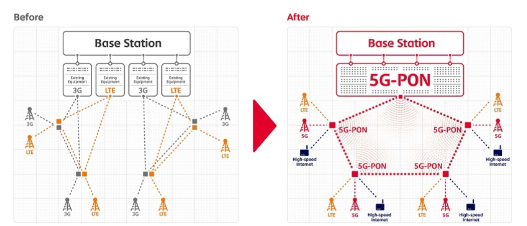
5G-PON: SK Telecom’s unified distribution network
SK Telecom has detailed a networking architecture based on wavelength division multiplexing-passive optical network (WDM-PON) technology that it says will simplify the rollout of 5G while delivering significant cost savings.
 The telecom operator has already deployed the networking architecture, dubbed 5G-PON, for its LTE network and is offering the design to the 5G network standards of the ITU-T.
“SK Telecom is already witnessing a great amount of cost reductions from the deployment of 5G-PON,” says Seungjoo Hong, manager of the Broadband Technology Lab at SK Telecom (pictured).
5G-PON
5G-PON provides a single distribution network for both cellular - LTE and 5G - and high-speed wireline broadband (see diagram).
 Source: SK Telecom
The architecture reduces networking costs by reusing existing fibre and optical filters while expanding capacity to support different and growing traffic streams. The architecture also uses passive nodes that do not require electrical power.
The 5G-PON network comprises three main elements: a central office terminal, the remote node and a tunable SFP pluggable module.
The central office terminal is located at the cellular base band unit (BBU) and performs such functions as wavelength conversion for WDM transmission, the monitoring of the optical link, and the management and configuration - location and order - of the remote nodes. The central office terminal also collects and analyses digital diagnostic monitoring information sent over an auxiliary management and control channel.
SK Telecom is already witnessing a great amount of cost reductions from the deployment of 5G-PON
The second element, the remote node, is a passive optical wavelength router, says Hong, and can be placed indoors or outdoors at a remote site. The remote node comprises a filter for coarse WDM (CWDM) and a filter for dense WDM (DWDM) and supports an optical ring topology between the first stage nodes - called the main radio node - as well as multi-stage node configurations such as a main and sub radio nodes (see the diagram below).
 Different 5G-PON configurations. SK Telecom favours a single-fibre ring arrangement. Source: SK Telecom
The central office terminal has knowledge of the order and location of the remote site nodes. This ensures a seamless service by performing delay equalisation due to optical path differences while executing ring protection switching within 50ms when a fibre is cut.
Meanwhile, the tunable SFP is installed at the cellular remote radio head (RRH). The tunable SFP is a low-cost design; it does not use a wavelength locker such that the SFP’s tunable laser is not dependent on a specific wavelength grid. The SFP is operated at the remote radio head using a software wavelength locking function that tracks the centre of the WDM filter using received optical power information from the central office terminal sent via an auxiliary management and control channel.
5G-PON has halved the cost of installation while operations and maintenance costs have been reduced 70 percent
CWDM architecture
5G-PON’s WDM-PON architecture uses CWDM with sub-channels.
The architecture can use existing installed fibre and filters while expanding capacity to a total of 256 wavelengths (16 sub-channels in each of 16 CWDM 20nm-wide bands), such that it can work alongside existing CWDM, DWDM and time-division multiplexing PON (TDM-PON) deployments.
“To expand network capacity in an area, operators can easily deploy a basestation using their existing fibre infrastructure, saving a great amount of installation cost,” says Hong. “5G-PON also allows operators to cover new areas with the least amount of cost.”
Hong says deploying 5G-PON has halved the cost of installation while operations and maintenance costs have been reduced 70 percent due to the intelligent operation and management of the passive nodes and the use of tunable SFPs at the remote sites.
SK Telecom has worked with local vendors including Solid, HFR, SunwaveTec and Coweaver to develop the 5G-PON architecture.
Status
The 5G-PON deployed for SK Telecom’s LTE front-haul network uses single-fibre bidirectional 3-gigabit and 6-gigabit 20km tunable SFPs that support 96 optical links on CPRI/ OBSAI interface channel cards.
Hong says that in 2018, SK Telecom will have bidirectional 10-gigabit tunable SFPs and will start developing of 25-gigabit bidirectional tunable SFPs and eCPRI interface channel cards for its 5G radio access network.
SK Telecom’s own preference is to use 5G-PON in a ring architecture to ensure service continuity in the event of a fibre cut. But depending on the operator, various topologies can be supported.
The operator plans to roll out 5G-PON in 85 areas nationwide, with further deployments expected thereafter.
TIP tackles the growing complexity of open design
The TIP chairman and vice president, technology innovation at Deutsche Telekom described how the relentless growth of IP traffic is causing production costs to rise yet the average revenues per subscriber for bundled communications services is flat or dipping. “Not a good situation to be in,” he said. The industry is also investing in new technologies including the rollout of 5G.
 Niall Robinson
The industry needs a radically different approach if it is to achieve capital efficiency, said Clauberg, and that requires talent to drive innovation. Garnering such talent needs an industry-wide effort and this is the motivation for TIP.
TIP
Established in 2016, TIP brings together internet giants Facebook and Microsoft with leading telecom operators, systems vendors, components players and others to co-develop open-source designs for telecoms. In the last year, TIP has added 200 companies to total over 500 members.
TIP used its second summit held in Santa Clara, California to unveil several new project groups. These include End-to-End Networking Slicing, Edge Computing, and Artificial Intelligence and Applied Machine Learning.
There are three main project categories within TIP: access, backhaul, and core and management. Access now includes six project groups including the new Edge Computing, backhaul has two, while core and management has three including the new network slicing and artificial intelligence initiatives. TIP has also established what it calls ecosystem acceleration centres and community labs.
“TIP is definitely bigger and, I think, better,” says Niall Robinson, vice president, global business development at ADVA Optical Networking. “As with any organisation there is always initial growing pains and TIP has gone through those.”
Open Optical Packet Transport
ADVA Optical Networking is a member in one of TIP’s more established projects, the Open Optical Packet Transport group which announced the 1-rack-unit Voyager packet transport and routing box last year.
OOPT itself comprises four work groups: Optical Line System, Disaggregated Transponders and Chips, Physical Simulation Environment and the Common API. A fifth group is being considered to tackle routing and software-defined interconnection.
Robinson highlights two activities of the OOPT’s subgroups to illustrate the scope and progress of TIP.
The Common API group in which Robinson is involved aims to bring commonality to the various open source groups’ application programming interfaces (APIs).
Open is great but there are so many initiatives out there that it is really not helping the market
The Open Networking Forum alone has several initiatives: the Central Office Rearchitected as a Data centre (CORD), the Open Networking Operating System (ONOS) SDN controller, the Open Core Model, and the Transport API. Other open initiatives developing APIs include OpenConfig set up by operators, the Open API initiative, and OpenROADM.
“Open is great but there are so many initiatives out there that it is really not helping the market,” says Robinson. An operator may favour a particular system vendor’s equipment that does not support a particular API. Either the operator or the vendor must then develop something, a situation in the case of an operator that can repeat itself many times. The goal of the Common API group’s work is to develop a mapping function between the software-defined networking (SDN) controller and equipment so that any SDN controller can use these industry-initiative APIs.
Robinson’s second example is the work of the OOPT’s Disaggregated Transponders and Chips group that is developing a transponder abstraction interface. The goal is to make it easier for vendors to benefit from the functionality of a transponder’s coherent DSP independent of the particular chip used.
“For ADVA, when we build our own gear we pick a DSP and we have to get our firmware to work with it,” says Robinson. “We can’t change that DSP easily; it’s a custom interface.”
The goal of the work is to develop a transponder abstraction interface that sits between the higher-level functionality software and the coherent DSP. The transponder vendor will interface its particular DSP to the abstraction interface that will then allow a network element’s software to configure settings and get optical monitoring data.
“It doesn’t care or even know what DSP is used, all it is talking to is this common transponder abstraction interface,” says Robinson.
Cassini and Voyager platforms
Edgecore Networks has contributed its packet transponder white box platform to the TIP OOPT group. Like Voyager, the platform uses the Broadcom StrataXGS Tomahawk 3.2 terabit switch chip. But instead of using built-in coherent interfaces based on Acacia’s AC-400 module, Cassini offers eight card slot options. Each slot can accommodate three module options: a coherent CFP2-ACO, a coherent CFP2-DCO or two QSFP28 pluggables. The Cassini platform also has 16 fixed QSFP28 ports.
Accordingly, the 1.5-rack-unit box can be configured as a 3.2 terabit switch using QSFP28 modules only or as a transport box with up to 1.6 terabits of client-side interfaces and 1.6 terabits of line-side coherent interfaces. This contrasts with the Voyager that uses up to 2 terabits of the switch capacity with its dozen 100-gigabit client-side interfaces and 800 gigabits of coherent line-side capacity.
There have also been developments with TIP’s Voyager box. Cumulus Network has replaced Snaproute to provide the platform’s Linux network operating system. ADVA Optical Networking, a seller of the Voyager, says the box will likely be generally available in the first quarter of 2018.
Robinson says TIP will ultimately be judged based on what it ends up delivering. “Eighteen months is not enough time for the influence of something like this to be felt,” he says.
TIP Summit 2017 talks, click here
ETSI embraces AI to address rising network complexity
The growing complexity of networks is forcing telecom operators and systems vendors to turn to machine intelligence for help. It has led the European Telecommunications Standards Institute, ETSI, to set up an industry specification group to define how artificial intelligence (AI) can be applied to networking.
“With the advent of network functions virtualisation and software-defined networking, we can see the eventuality that network management is going to get very much more complicated,” says Ray Forbes, convenor of the ETSI Industry Specification Group, Experimental Network Intelligence (ISG-ENI).
 Source: ETSI
The AI will not just help with network management, he says, but also with the introduction of services and the more efficient use of network resources.
Visibility of events at many locations in the network will be needed with the deployment of network functions virtualisation (NFV), says Forbes. In current networks, a large switch may serve hundreds of thousands of users but with NFV, virtual network functions will be at many locations. The ETSI group will look at how AI can be used to manage and control this distributed deployment of virtual network functions, says Forbes.
The group’s work has started by inviting interested parties to bring and discuss use cases from which a set of requirements will be generated. In parallel, the group is looking at AI techniques.
The aim is to use computing to derive data from across the network. The data will be analysed, and by having 'context awareness', the machine intelligence will compute various scenarios before presenting the most promising ones for consideration by the network management team. “The process is collecting data, analysing it, testing out various scenarios and then advising people on what would happen in the better scenarios,” says Forbes.
With the advent of NFV and SDN, we can see the eventuality that network management is going to get very much more complicated
ETSI's goal is to make it easier for operators to deploy services quickly, reroute around networking faults, and make better use of networking resources. “In very large cities like Shanghai and Tokyo, where there are populations of 25 million, there is a need for this,” says Forbes. “In London, with about 12 million people, there is still a need but not quite so quickly.”
Operators and system vendors have some understanding of AI but there is a learning curve in bringing more and more AI experts on board, says Forbes: "Hence, we are trying to involve various universities in the research project."
Project schedule
The ISG-ENI's initial document work will be followed by defining the architecture and specifying the parameters needed to measure the network and the 'intelligence' of the scenarios.
“ETSI has a two-year project with the possibility of an extension,” says Forbes, with AI deployed in networks as early as 2019.
Forbes says open-source software to add AI to networks could be available as soon as 2018. Such open-source software will be developed by operators and systems vendors rather than ETSI.