
Relentless traffic growth leads to a ROADM rethink
Technology briefing: ROADMs
Lumentum has developed an optical switch to enable reconfigurable optical add-drop multiplexers (ROADMs) to cope with the traffic growth expected over the next decade.
The company’s MxN wavelength-selective switch (WSS) will replace the existing multicast switch used in colourless, directionless and contentionless ROADMs. The Lumentum TrueFlex 8x24 twin switch will enable networking nodes of 400-terabit capacity.
“This second-generation switch is what will take us into the 100 gigabaud and super-channel era of network scalability,” says Brandon Collings, CTO of Lumentum.
ROADMs
ROADMs sit at the mesh nodes in an optical network. Their function is to pass lightpaths destined for other nodes in the network - referred to as optical bypass - and enable the adding and dropping of wavelengths at the node. Such add/drops may be rerouted traffic or provisioned new services.
As network traffic continues to grow, so do the degrees of a ROADM and the ports of its sub-systems. The degree of a ROADM is defined to the number of connections or fibre pairs it can support. In the diagram, a ROADM of degree three is shown.
 A multicast switch-based 3-degree CDC ROADM. Source Lumentum.
It is rare to encounter more than five or six fibre routes leaving any given mesh node in a network, says Lumentum. “But in those fibre routes there is typically a large number of fibres - 64 or 128,” says Collings. “Operators deploy a conduit of fibre between cities.”
When the C-band fills up, an operator will light another fibre pair, taking up another of the ROADM’s degrees. ROADMs built today have 16 degrees. And since a fibre’s C-band can occupy some 30 terabits of data, this is how 400-terabit mesh nodes will be achieved.
“That is a pretty big node but that is the end [of life] capacity,” says Collings. “I don’t think you will find a 400-terabit node today but we build our networks so that they get there, five to eight years from when they are deployed.”
This raises another issue: the length of time it takes for any generational change of a ROADM design to take hold in the network.
“When a new approach comes along, it takes a couple of years for everyone to figure out how they will use it,” says Collings. Then, once a decision is made, it takes another two years to deploy followed by five to eight years before the ROADM node is filled.
“Nothing happens quickly in this business,” says Collings. “But the upside, from a business point of view, is that as things are designed in, they have a long deployment cycle.”
Lumentum illustrates the point with its own products.
The company is seeing growing demand for its dual TrueFlex WSS deployed in route-and-select ROADM architectures. “But we are still seeing growth on the older broadcast-and-select architectures underpinned by singe 1x9 WSSes,” says James Goodchild, director, product line management for wavelength management products at Lumentum.
CDC ROADMs
A colourless, directionless and contentionless (CDC) ROADM uses a twin multicast switch for the wavelength add and drop functions. The input fibre to each degree’s WSS is connected to the output path WSS of each of the ROADM’s other degrees. The input WSS also connects to the drop multicast switch (see diagram above).
Using a WSS on the input path means that only wavelengths of interest are routed to the WSS’ output ports. Hence the ROADM’s reference as a route-and-select architecture.
Using a 1xN splitter array instead of a WSS for the input path results in a broadcast-and-select ROADM. Here, the input fibre’s wavelengths are broadcast to all the N output ports. The high optical loss associated with the splitters is the main reason why CDC ROADM designs have transitioned to the WSS-based route-and-select architecture.
This second-generation switch is what will take us into the 100 gigabaud and super-channel era of network scalability
However, there is still an optical loss issue to be contended with, introduced by the add or drop multicast switch. Accordingly, along with the twin multicast switch are two arrays of erbium-doped fibre amplifiers (EDFAs). One EDFA array is on the drop ports to the MxN multicast switch and the second amplifier array boosts the outputs of the add-path multicast switch before their transmission into the network.
The MxN multicast switch comprises 1xN splitter arrays, N being the number of add-drop ports, and Mx1 selection switches where M is the number of directions the ROADM supports. A typical multicast switch is 8x16: eight being the ROADM’s number of directions and 16 the drop-port count.
Each of the N splitter arrays sends the signals on a drop port to all the Mx1 selection switches where each one pulls off the channel to be dropped. Having a selection switch at each of the multicast switch’s N drop ports is what enables contentionless operation, the avoidance of a collision when the same wavelength is droppedat a node from different degree directions.
MxN switch
Lumentum’s decision to develop the MxN switch to replace the multicast switch follows its study to understand how optical transmission networks will evolve with continual traffic growth.
One development is the adoption of higher-baud-rate, higher-capacity coherent transmissions that require wider channel widths. A 400-gigabit wavelength requires a 75GHz channel compared to the standard 50GHz fixed grid used for 100- and 200-gigabit transmissions. Future transmission speeds of 800 gigabits will use two such channels or 150GHz of spectrum, while a 1 terabit signal is expected to occupy 300GHz of fibre spectrum. “This is how we anticipate coherent transmission evolving,” says Collings.
Moving to wider channels also benefits the ROADM’s cost. If operators continued to use 50GHz channels, the channel count would grow exponentially with the growth in traffic. In contrast, adopting wider channels means the add-drop port count grows only linearly with traffic. “Using wider channels, the advantage is you don't have to support 600 ports of add-drop in your ROADM networks,” says Collings.
But wider channels means greater amplification demands on the EDFA arrays, an issue that will only worsen over time.
Multicast switch-based designs don’t support the wider channels we know are coming
Losing the amp
Because the power spectral density is constant, the power in a channel increases proportionally with its width. For example, a 75GHz channel has 2dB more power compared to a 50GHz channel spacing, a 150GHz channel 5dB more while a 300GHz channel has an extra 8dB.
The EDFA array is engineered to handle the worst case power requirement that occurs when all 16 optical transceivers into the multicast switch go to the same ROADM degree. Here the EDFA must be able to boost all 16 channels.
For a multicast switch with 16 ports, 22dBm amplification is needed for a 150GHz channel which requires going from an uncooled pump design to a cooled pump one. Equally, 25dBm amplification is needed for 300GHz channels. And as the number of degrees grows, so do the demands on the amplification until no practical amplifier design is possible (see diagram).
 The EDFA requirements to compensate for the optical loss of the multicast switch. The complexity of the EDFA design grows with the multicast switch's port count until it becomes insupportable. Source: Lumentum.
“This is not an issue today because we use very modest-sized channels and we engineer our systems to accommodate them,” says Collings. “But if you look forward, you realise they [multicast switch-based designs] don’t support the wider channels we know are coming.”
Using a WSS-based MxN switch solves this issue because, as with the input port WSS of a route-and-select architecture, the switch has a lower optical loss - under 8dB - compared to the 17dB of the splitter-based multicast switch.
The sub-8dB loss is below the threshold where amplification is needed: the optical signal is sufficiently strong at the drop port to be received, as are the added signals for transmission into the network. The resulting removal of the EDFAs simplifies greatly the complexity, size and cost of the CDC ROADM.
“The MxN is a WSS - it’s a router - so it sends all of the light in the direction it is supposed to go,” says Collings. “You can push through the MxN switch channels of any width and of any power because there is no amplifier that needs to be there and be designed appropriately."
The resulting second-generation CDC ROADM design is shown below.
 Source: Lumentum
Lumentum's Goodchild says the 8x24 twin implementation of the MxN switch will be available in the first quarter of 2019.
“Certain systems vendors already have access to samples,” says Goodchild.
Further reading
2D WSSes, click here
ROADMs and their evolving amplification needs, click here
ROADMs and their evolving amplification needs
Technology briefing: ROADMs and amplifiers
Oclaro announced an add/drop routing platform at the recent OFC/NFOEC show. The company explains how the platform is driving new arrayed amplifier and pumping requirements.
 A ROADM comprising amplification, line-interfaces, add/ drop routing and transponders. Source: Oclaro
Agile optical networking is at least a decade-old aspiration of the telcos. Such networks promise operational flexibility and must be scalable to accommodate the relentless annual growth in network traffic. Now, technologies such as coherent optical transmission and reconfigurable optical add/drop multiplexers (ROADMs) have reached a maturity to enable the agile, mesh vision.
Coherent optical transmission at 100 Gigabit-per-second (Gbps) has become the base currency for long-haul networks and is moving to the metro. Meanwhile, ROADMs now have such attributes as colourless, directionless and contentionless (CDC). ROADMs are also being future-proofed to support flexible grid, where wavelengths of varying bandwidths are placed across the fibre's spectrum without adhering to a rigid grid.
Colourless and directionless refer to the ROADM's ability to transmit or drop any light path from any direction or degree at any network interface port. Contentionless adds further flexibility by supporting same-colour light paths at an add or a drop.
"You can't add and drop in existing architectures the same colour [light paths at the same wavelength] in different directions, or add the same colour from a given transponder bank," says Bimal Nayar, director, product marketing at Oclaro's optical network solutions business unit. "This is prompting interest in contentionless functionality."
The challenge for optical component makers is to develop cost-effective coherent and CDC-flexgrid ROADM technologies for agile networks. Operators want a core infrastructure with components and functionality that provide an upgrade path beyond 100 Gigabit coherent yet are sufficiently compact and low-power to minimise their operational expenditure.
ROADM architectures
ROADMs sit at the nodes of a mesh network. Four-degree nodes - the node's degree defined as the number of connections or fibre pairs it supports - are common while eight-degree is considered large.
The ROADM passes through light paths destined for other nodes - known as optical bypass - as well as adds or drops wavelengths at the node. Such add/drops can be rerouted traffic or provisioned new services.
Several components make up a ROADM: amplification, line-interfaces, add/drop routing and transponders (see diagram, above).
"With the move to high bit-rate systems, there is a need for low-noise amplification," says Nayar. "This is driving interest in Raman and Raman-EDFA (Erbium-doped fibre amplifier) hybrid amplification."
The line interface cards are used for incoming and outgoing signals in the different directions. Two architectures can be used: broadcast-and-select and route-and select.
With broadcast-and-select, incoming channels are routed in the various directions using a passive splitter that in effect makes copies the incoming signal. To route signals in the outgoing direction, a 1xN wavelength-selective switch (WSS) is used. "This configuration works best for low node-degree applications, when you have fewer connections, because the splitter losses are manageable," says Nayar.
For higher-degree node applications, the optical loss using splitters is a barrier. As a result, a WSS is also used for the incoming signals, resulting in the route-and-select architecture.
Signals from the line interface cards connect to the routing platform for the add/drop operations. "Because you have signals from any direction, you need not a 1xN WSS but an LxM one," says Nayar. "But these are complex to design because you need more than one switching plane." Such large LxM WSSes are in development but remain at the R&D stage.
Instead, a multicast switch can be used. These typically are sized 8x12 or 8x16 and are constructed using splitters and switches, either spliced or planar lightwave circuit (PLC) based .
"Because the multicast switch is using splitters, it has high loss," says Nayar. "That loss drives the need for amplification."

Add/drop platform
With an 8-degree-node CDC ROADM design, signals enter and exit from eight different directions. Some of these signals pass through the ROADM in transit to other nodes while others have channels added or dropped.
In the Oclaro design, an 8x16 multicast switch is used. "Using this [multicast switch] approach you are sharing the transponder bank [between the directions]," says Nayar.
 The 8-degree node showing the add/drop with two 8x16 multicast switches and the 16-transponder bank. Source: Oclaro
A particular channel is dropped at one of the switch's eight input ports and is amplified before being broadcast to all 16, 1x8 switches interfaced to the 16 transponders.
It is the 16, 1x8 switches that enable contentionless operation where the same 'coloured' channel is dropped to more than one coherent transponder. "In a traditional architecture there would only be one 'red' channel for example dropped as otherwise there would be [wavelength] contention," says Nayar.
The issue, says Oclaro, is that as more and more directions are supported, greater amplification is needed. "This is a concern for some, as amplifiers are associated with extra cost," says Nayar.
The amplifiers for the add/drop thus need to be compact and ideally uncooled. By not needing a thermo-electrical cooler, for example, the design is cheaper and consumes less power.
The design also needs to be future-proofed. The 8x16 add/ drop architecture supports 16 channels. If a 50GHz grid is used, the amplifier needs to deliver the pump power for a 16x50GHz or 800GHz bandwidth. But the adoption of flexible grid and super-channels, the channel bandwidths will be wider. "The amplifier pumps should be scalable," says Nayar. "As you move to super-channels, you want pumps that are able to deliver the pump power you need to amplify, say, 16 super-channels."
This has resulted in an industry debate among vendors as to the best amplifier pumping scheme for add/drop designs that support CDC and flexible grid.
EDFA pump approaches
Two schemes are being considered. One option is to use one high-power pump coupled to variable pump splitters that provides the required pumping to all the amplifiers. The other proposal is to use discrete, multiple pumps with a pump used for each EDFA.
 Source: Oclaro
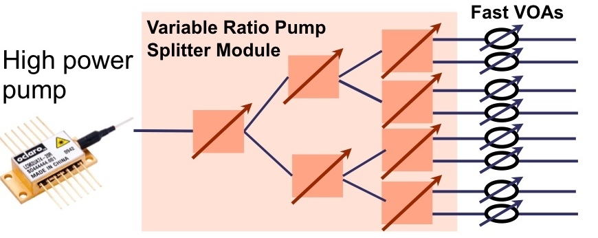
In the first arrangement, the high-powered pump is followed by a variable ratio pump splitter module. The need to set different power levels at each amplifier is due to the different possible drop scenarios; one drop port may include all the channels that are fed to the 16 transponders, or each of the eight amplifiers may have two only. In the first case, all the pump power needs to go to the one amplifier; in the second the power is divided equally across all eight.
Oclaro says that while the high-power pump/ pump-splitter architecture looks more elegant, it has drawbacks. One is the pump splitter introduces an insertion loss of 2-3dB, resulting in the pump having to have twice the power solely to overcome the insertion loss.
The pump splitter is also controlled using a complex algorithm to set the required individual amp power levels. The splitter, being PLC-based, has a relatively slow switching time - some 1 millisecond. Yet transients that need to be suppressed can have durations of around 50 to 100 microseconds. This requires the addition of fast variable optical attenuators (VOAs) to the design that introduce their own insertion losses.
"This means that you need pumps in excess of 500mW, maybe even 750mW," says Nayar. "And these high-power pumps need to be temperature controlled." The PLC switches of the pump splitter are also temperature controlled.
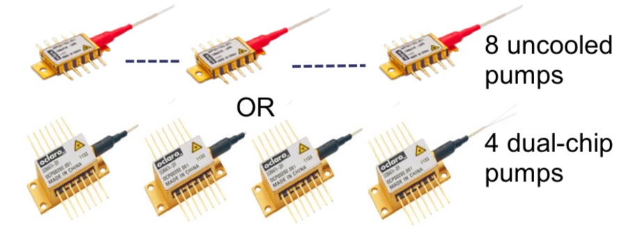
The individual pump-per-amp approach, in contrast, in the form of arrayed amplifiers, is more appealing to implement and is the approach Oclaro is pursuing. These can be eight discrete pumps or four uncooled dual-chip pumps, for the 8-degree 8x16 multicast add/drop example, with each power level individually controlled.
 Source: Oclaro
Oclaro says that the economics favour the pump-per-amp architecture. Pumps are coming down in price due to the dramatic price erosion associated with growing volumes. In contrast, the pump split module is a specialist, lower volume device.
"We have been looking at the cost, the reliability and the form factor and have come to the conclusion that a discrete pumping solution is the better approach," says Nayar. "We have looked at some line card examples and we find that we can do, depending on a customer’s requirements, an amplified multicast switch that could be in a single slot."